Caliper gauge

a technology of caliper and caliper plate, applied in the field of caliper plate, can solve the problems of difficult to keep the measurement force constant against the reverse rotation, the accuracy of the measurement is not guaranteed, and the measurement force applied when the measuring jaws hold the object is sometimes critical, etc., to achieve the effect of high accuracy and constant measuring for

Active Publication Date: 2009-05-19
MITUTOYO CORP
View PDF17 Cites 39 Cited by
  • Summary
  • Abstract
  • Description
  • Claims
  • Application Information

AI Technical Summary

Benefits of technology

[0012]An object of the present invention is to provide a caliper gauge capable of keeping constant measuring force irrespective of which one of inside and outside measuring jaws is used during measurement process.
[0014]According to the present invention, the constant-pressure unit includes the saw-toothed projections provided on the inner circumference of the outer roller; the plate spring provided on the outer circumference of the inner roller at the midsection thereof and contacted with the saw-toothed projections of the outer roller on both ends thereof. Accordingly, an end of the plate spring interconnects the outer roller and the inner roller when the outer roller is rotated in one direction to transmit the rotation of the outer roller to the inner roller and allows free rotation of the outer roller relative to the inner roller when more than a predetermined load is applied on the inner roller. Further, the other end of the plate spring interconnects the outer roller and the inner roller against the rotation of the outer roller in the other direction to transmit the rotation of the outer roller to the inner roller and allows free rotation of the outer roller relative to the inner roller when more than a predetermined load is applied on the inner roller. Accordingly, constant measuring force can be kept irrespective of which of the outside measuring jaws and the inside measuring jaws are used, thus achieving highly accurate measurement.
[0018]According to the above arrangement, in the same manner as an ordinary caliper gauge, the main scale is gripped with one hand and the slider is moved along the main scale while applying thumb on the slider. Further, the slider can be minutely moved via the feeding mechanism by pressing the feeding mechanism to bring the feeding mechanism into contact with the main scale as necessary, thus keeping the constant measuring force. Accordingly, highly accurate measurement can be achieved without impairing operation feeling of a usual caliper gauge.

Problems solved by technology

In such a caliper gauge, measuring force applied when the measuring jaws hold the object is sometimes of critical issue.
Especially, when the object is made of soft material such as rubber and plastic, the object is greatly deformed, which results in variation of measured value in accordance with difference in the measuring force, thereby rendering accurate measurement difficult.
However, there is, for instance, the following problem in the caliper gauge of the above document.
Though the ratchet mechanism keeps a constant measuring force against the rotation of the pressing roller in one direction, the measuring force cannot be kept constant against the reverse rotation.

Method used


Image

  • Caliper gauge
  • Caliper gauge
  • Caliper gauge

Examples


Embodiment Construction

)

[0023]An embodiment of the present invention will be described below with reference to the attached drawings.

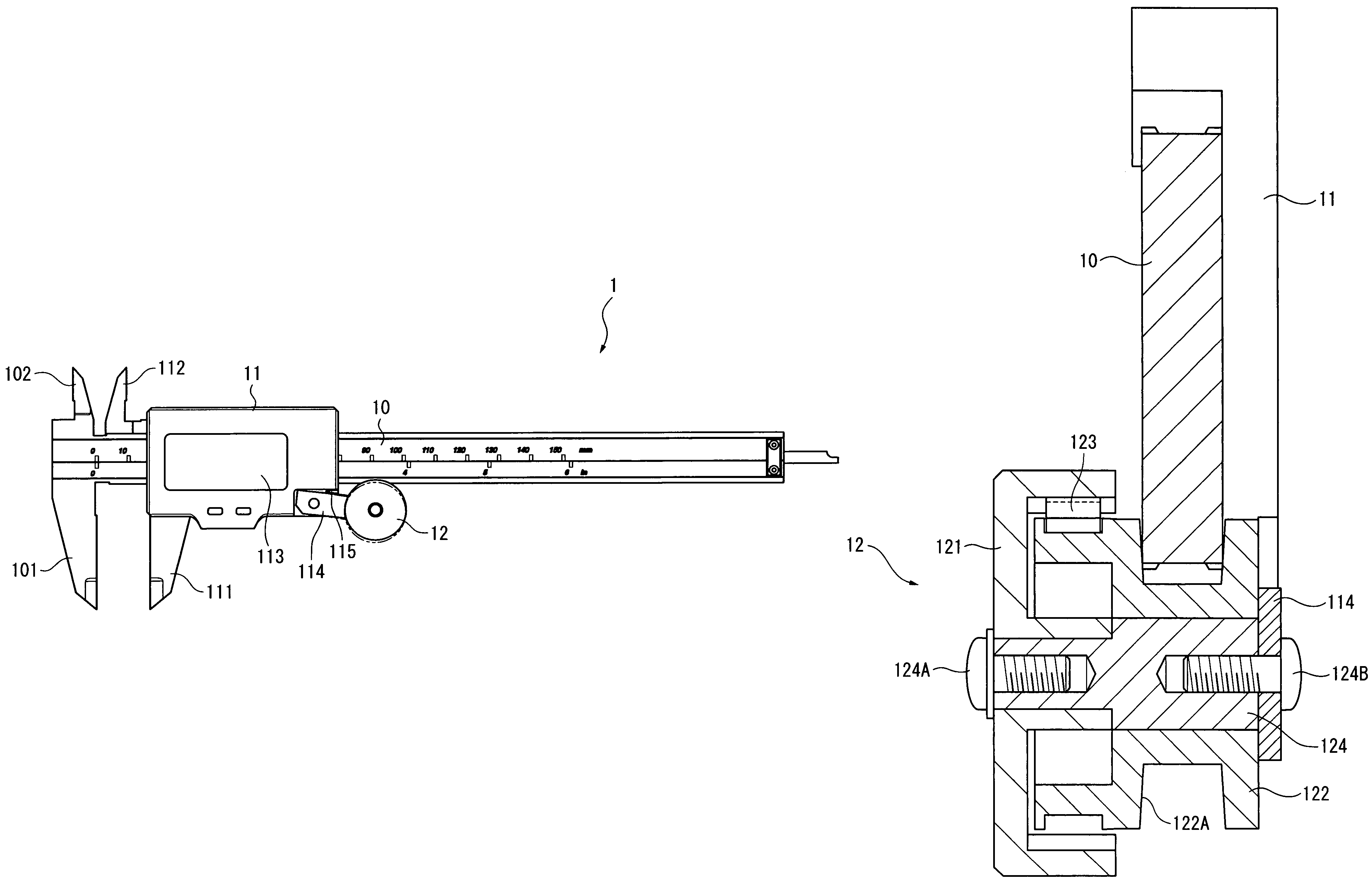
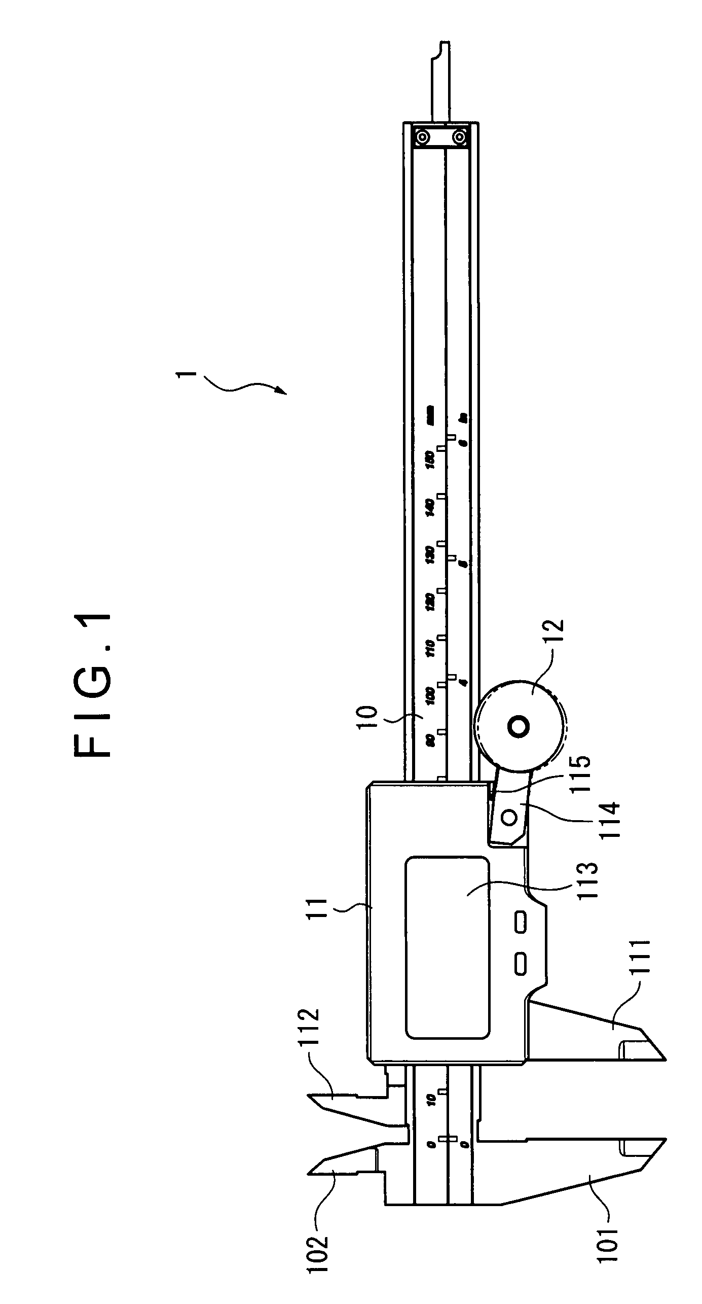
[0024]As shown in FIG. 1, the caliper gauge 1 according to the present embodiment includes a main scale 10, a slider 11 movably provided to the main scale 10, a display unit 113 for displaying the displacement of the slider 11 relative to the main scale 10, and a feeding mechanism 12 that moves the slider 11 along the main scale 10.

[0025]The main scale 10 is provided with an outside measuring jaw 101 and an inside measuring jaw 102 on a longitudinal end thereof.

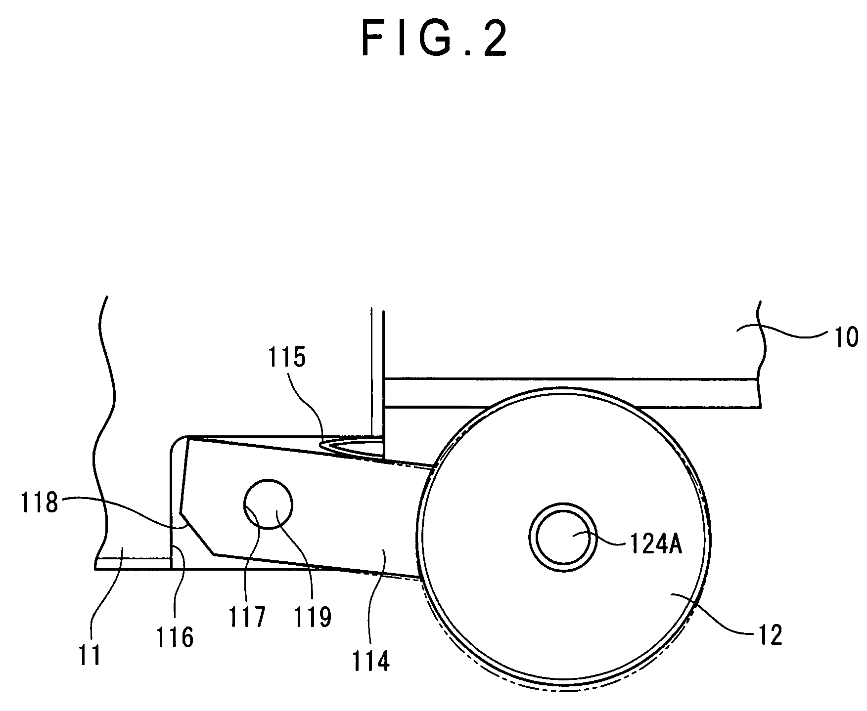
[0026]The slider 11 includes an outside measuring jaw 111 and an inside measuring jaw 112, a display unit 113, a support unit 114 that supports the feeding mechanism 12 in a manner movable toward and away from the main scale 10, and a biasing unit 115 that biases the support unit 114 in a direction for the feeding mechanism 12 to be away from the main scale 10.

[0027]The outside measuring jaw 111 and the inside measuri...


PUM


Abstract

A caliper gauge (1) includes a feeding mechanism (12) that moves a slider (11) along a main scale (10), in which the feeding mechanism (12) includes: an outer roller (121); an inner roller (122) provided in a manner rotatable around a rotary axis of the outer roller (121) to be in contact with the main scale (10); and a constant-pressure unit (123) that transmits the rotation of the outer roller (121) to the inner roller (122) and allows free rotation of the outer roller (121) relative to the inner roller (122) when more than a predetermined load is applied on the inner roller (122), the constant-pressure unit (123) including: saw-toothed projections provided on an inner circumference of the outer roller (121); and a plate spring fixed on an outer circumference of the inner roller (122) at a midsection thereof and contacted with the saw-toothed projections of the outer roller (121) on both ends thereof.

Description

BACKGROUND OF THE INVENTION[0001]1. Field of the Invention[0002]The present invention relates to a caliper gauge. More specifically, the present invention relates to a caliper gauge that holds an object to be measured with a constant measuring force.[0003]2. Description of Related Art[0004]A caliper gauge includes a main scale having a first measuring jaw, a slider having a second jaw, the slider movably provided on the main body relative to the main body, and a display unit that displays the displacement of the slider relative to the main body.[0005]In order to measure an object, the main scale is gripped by one hand and the slider is moved along the main scale while applying thumb on the slider to bring inside or outside jaws provided on the main scale and the slider into contact with target portions of the object to be measured. The dimension and the like of the object can be measured by the value displayed on the display unit.[0006]In such a caliper gauge, measuring force applie...

Claims


Application Information

Patent Timeline
Patent Type & Authority Patents(United States)
IPC IPC(8): G01B5/02
CPCF16D7/048G01B3/205
Inventor SAITO, OSAMUSUZUKI, MASAMICHI
Owner MITUTOYO CORP
Why Eureka
Try Eureka