Light source having an LED and a luminescence conversion body and method for producing the luminescence conversion body

a technology of luminescence and conversion body, which is applied in the direction of discharge tube luminescnet screen, energy-saving lighting, sustainable buildings, etc., can solve the problem of photochemical instability of epoxy resin, and achieve the effect of high light power and high light power

Active Publication Date: 2009-06-30
OSRAM OPTO SEMICON GMBH & CO OHG
View PDF11 Cites 48 Cited by
  • Summary
  • Abstract
  • Description
  • Claims
  • Application Information

AI Technical Summary

Benefits of technology

[0018]In one particular refinement, the ceramic body has crystallites with a grain size from the range of 1 μm to 100 μm inclusive. The grain size is an equivalent diameter of the crystallites of a microstructure of a ceramic. The grain size is preferably 10 μm to 50 μm. This grain size enables efficient luminescence conversion. Furthermore, the ceramic grains of the base material and / or the ceramic grains of the luminescent material may function as scattering centers by producing suitably dimensioned pores in accordance with the theoretical density chosen.
[0027]In particular, the optical element is advantageously a lens. The lens may be of concave or convex form in this case. In this way, the surface section can have a focusing or defocusing effect on the primary and secondary radiation.
[0036]To summarize, the invention affords the following essential advantages: the light source having the LED and the ceramic, translucent luminescence conversion body is distinguished by a high light power. The luminescence conversion body is thermally and photochemically stable. The high light power is therefore maintained even in the event of relatively long operation of the light source. The luminescence conversion body may have optical elements such as a lens or scattering centers.

Problems solved by technology

The epoxy resin is photochemically unstable.

Method used


Image

  • Light source having an LED and a luminescence conversion body and method for producing the luminescence conversion body
  • Light source having an LED and a luminescence conversion body and method for producing the luminescence conversion body
  • Light source having an LED and a luminescence conversion body and method for producing the luminescence conversion body

Examples


Embodiment Construction

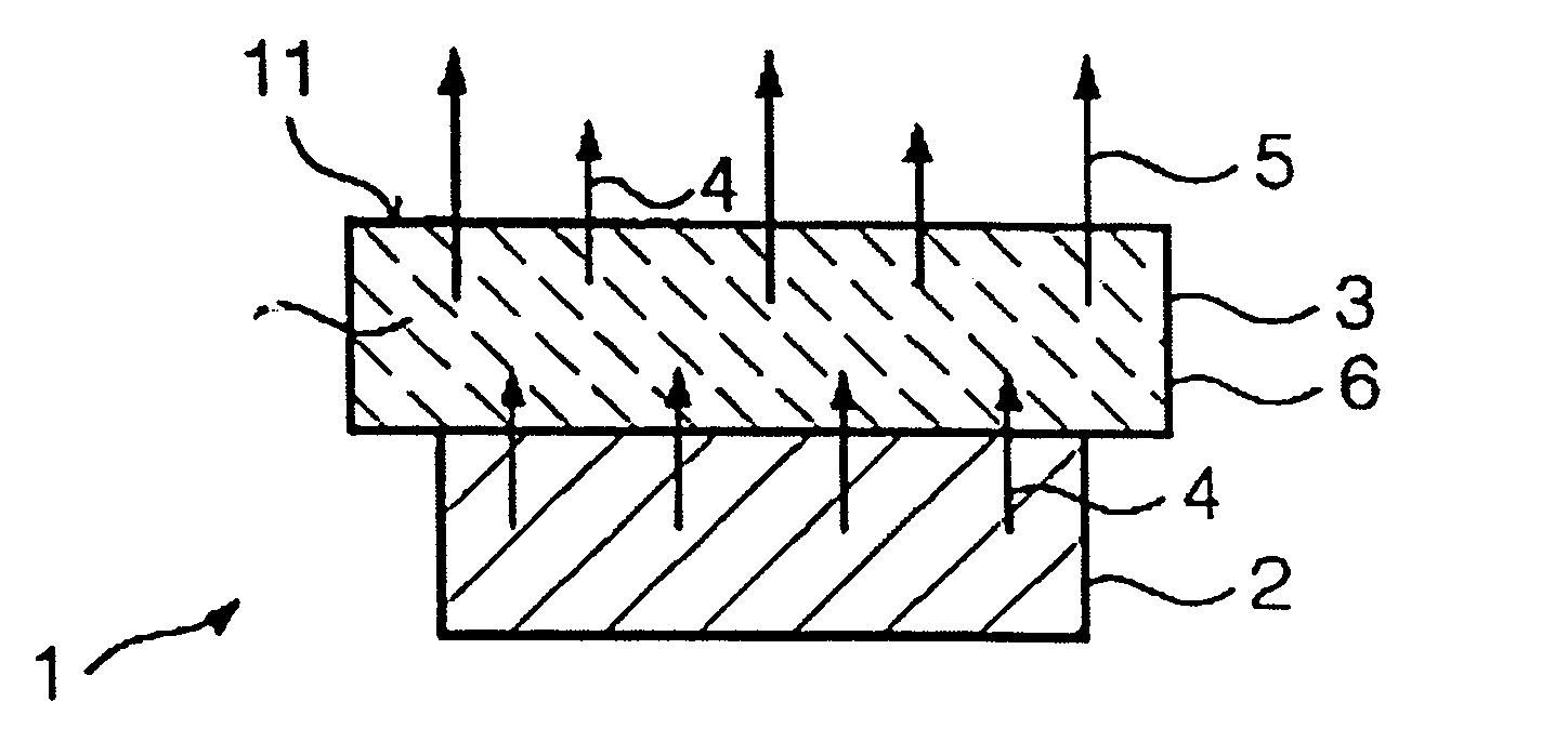
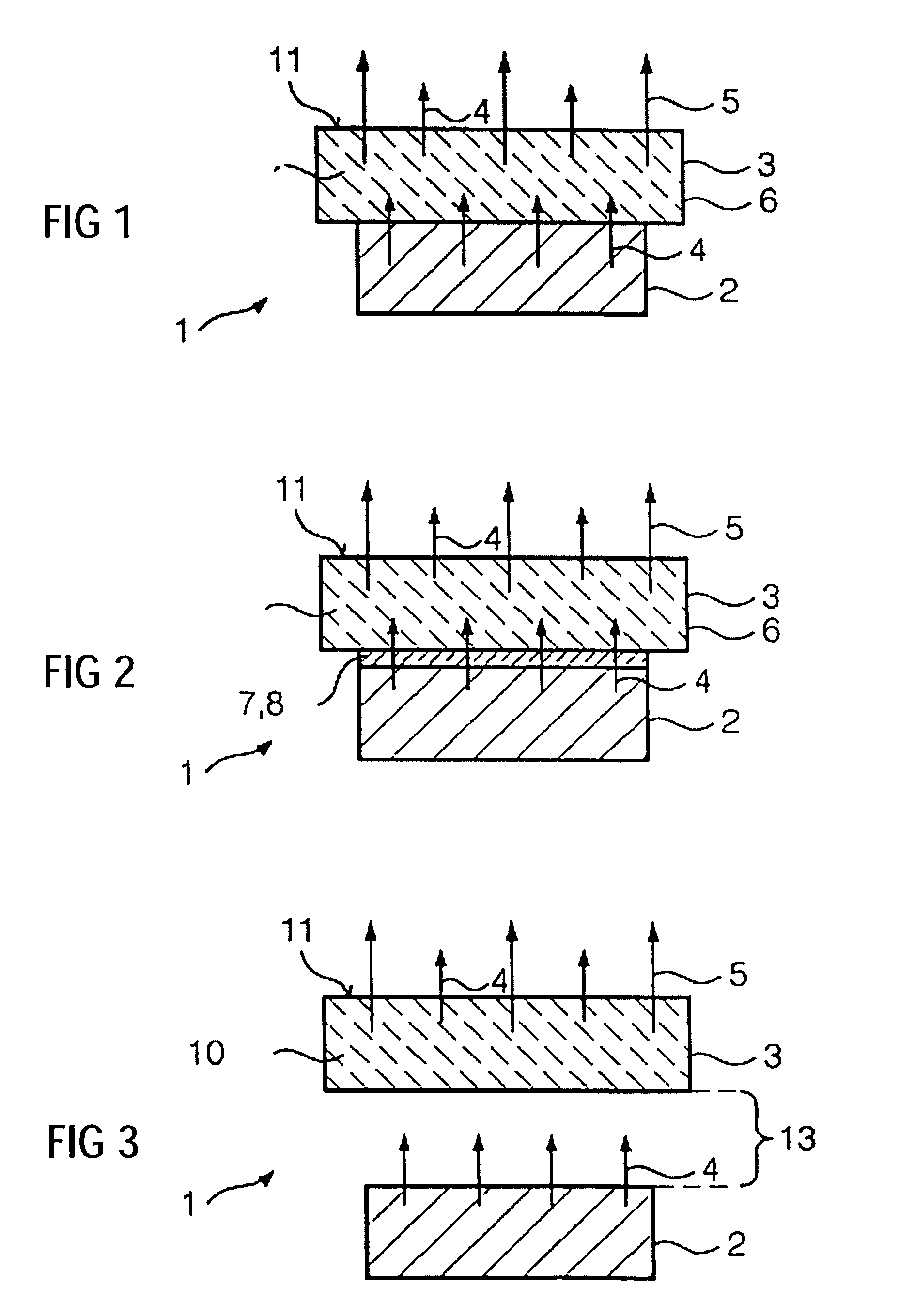
[0042]The light source 1 in FIG. 1 is a luminescence conversion LED that radiates white light. It comprises an LED 2 and a luminescence conversion body 3. The LED 2 has GaInN as semiconductor material. The LED 2 emits blue light with an intensity maximum at about 450 nm as primary radiation 4.

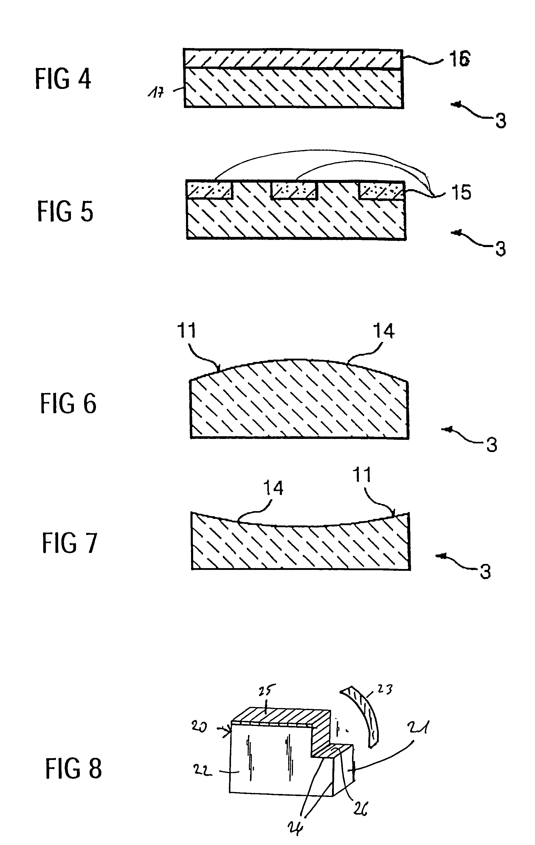
[0043]The luminescence conversion body 3 is a polycrystalline ceramic body having a ceramic density of about 95% of the theoretical density. The ceramic body 3 comprises ceramic particles, that is to say crystallites, having an average grain size of 10 μm to 20 μm (understood as equivalent diameter). The base material of the ceramic body 3 is an yttrium aluminum garnet. The base material is homogeneously doped with Ce for activation purposes. The Ce-doped, still ceramic base material functions as luminescent material which converts the primary radiation 4 of the LED 2 into the secondary radiation 5. The secondary radiation 5 emitted by the luminescent material has an intensity maximum—dependent...


PUM

PropertyMeasurementUnit
grain sizeaaaaaaaaaa
temperatureaaaaaaaaaa

Abstract

A light source, having at least one LED for emitting a primary radiation and at least one luminescence conversion body having at least one luminescent material for converting the primary radiation into a secondary radiation. The luminescence conversion body is a polycrystalline ceramic body which itself acts partly or completely as luminescent material by virtue of at least part of the base material which forms the ceramic body being activated by a dopant.

Description

TECHNICAL FIELD[0001]The invention relates to a light source, having at least one LED for emitting a primary radiation and at least one luminescence conversion body having at least one luminescent material for converting the primary radiation into a secondary radiation. A method for producing the luminescence conversion body is furthermore specified.PRIOR ART[0002]A light source of the type mentioned is disclosed in DE 196 38 667 A1. The light source is referred to as a luminescence conversion LED. The LED (Light Emitting Diode) of the light source has, as active layer, for example a semiconductor layer made of gallium indium nitride (GaInN). Electrical driving causes a primary radiation from a first wavelength range to be emitted from this layer. The LED emits “blue” light, for example. The intensity maximum of the primary radiation is about 450 nm. The primary radiation is converted into a secondary radiation with the aid of a luminescent material. The luminescent material is for ...

Claims


Application Information

Patent Timeline
Patent Type & Authority Patents(United States)
IPC IPC(8): H01L29/12H01L33/00H01L29/22C09K11/08C09K11/62C09K11/80H01L33/50H01L33/58
CPCC04B35/44C04B2235/3225C04B2235/3229C04B2235/764C04B2235/77C04B2235/786C04B2235/9653H01L33/502H01L33/58C09K11/7774H01L33/505Y02B20/00
Inventor ROSSNER, WOLFGANGWESSLER, BERIT
Owner OSRAM OPTO SEMICON GMBH & CO OHG
Why Eureka
Try Eureka