LED package and backlight unit using the same

a technology of led package and backlight unit, which is applied in the direction of spectral modifiers, refractors, lighting and heating apparatus, etc., can solve the problems of increasing manufacturing costs, spatial and environmental limitations of mercury use, complex lens shape, etc., and achieves simple lens shape and increased beam angle

Active Publication Date: 2009-09-01
SAMSUNG ELECTRONICS CO LTD
View PDF4 Cites 13 Cited by
  • Summary
  • Abstract
  • Description
  • Claims
  • Application Information

AI Technical Summary

Benefits of technology

[0014]The present invention has been made to solve the foregoing problems of the prior art and therefore an object of certain embodiments of the present invention is to provide a an LED package which can uniformly emit light without any bright spots formed in an output screen, have an increased beam angle with a simpler shape of lens, and minimize a mixing region where different colors of light beams are mixed, thereby achieving miniaturization, and a backlight unit using the same.

Problems solved by technology

In the case of using a Cold Cathode Fluorescent Lamp (CCFL) for a light source of the LCD, there are spatial and environmental limitations with use of mercury.
However, in the backlight unit with the above configuration, the LED package 1 refracts light laterally using the difference in the refractive indices of the lens 20 and thus cannot completely block the light beams emitted upward through a central portion.
To eliminate such bright spots, a separate sheet is required, increasing the manufacturing costs.
Moreover, the complex shape of the lens 20 requires a difficult manufacturing process and entails limitations in the lens material.
Further, in the case of using the above described lens 20, a large-sized LED 30 of at least 1 mm2 is suitable, which however results in low light efficiency.

Method used


Image

  • LED package and backlight unit using the same
  • LED package and backlight unit using the same
  • LED package and backlight unit using the same

Examples


second embodiment

[0050]FIG. 5 is a sectional view illustrating an LED package according to the present invention.

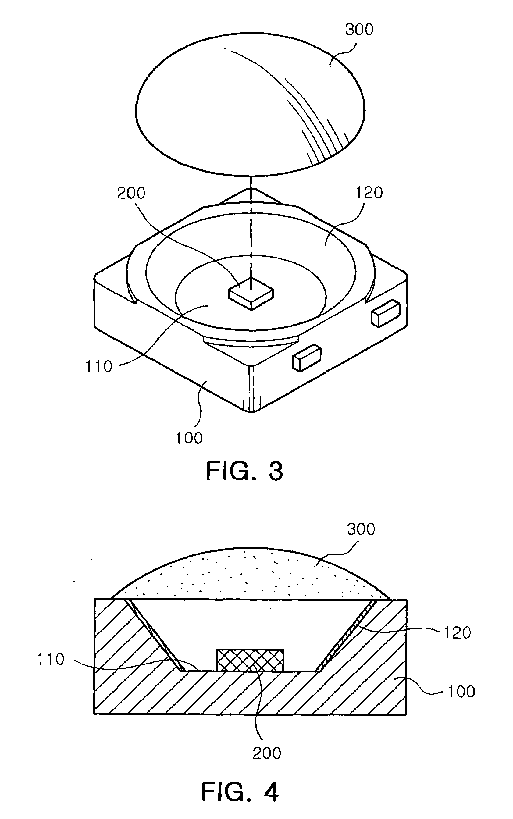
[0051]As shown in FIGS. 3 and 4, the lens 300 applied to the LED package according to the present invention can be separately manufactured from the housing 100 and then seated on an upper surface of the housing 100 afterwards, or as shown in FIG. 5, can be injected to fill inside the seating recess 110.

[0052]As shown in FIG. 5, in the case of filling inside the seating recess 110, the lens 300 may be made of a filler having a predetermined refractive index. In this case, the filler naturally forms a convex surface due to surface tension, thereby completing a shape of the lens 300 without further machining, which allows an easy fabrication process of the lens 300 irrespective of the size and shape of the seating recess 110.

[0053]In the embodiment shown in FIG. 5, the seating recess 110 is filled with a single material to fabricate the lens 300, but if it is necessary to adjust the refracti...

third embodiment

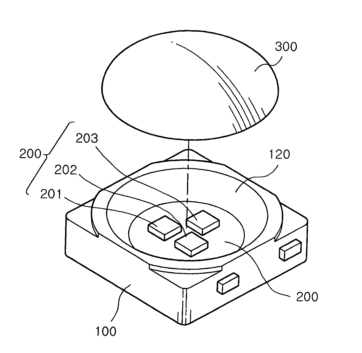
[0059]FIG. 8 is a perspective view illustrating an LED package according to the present invention.

[0060]The LED package according to the present invention may be configured to include a plurality of LEDs 200, i.e., a red LED 201, a green LED 202 and a blue LED 204 mounted inside the seating recess 110.

[0061]With the plurality of LEDs 201, 202 and 203 mounted inside the single seating recess 110 to mix different colors in the housing 100, the color mixing region is advantageously shortened, which in turn allows realizing white light with a single LED package.

[0062]Here, the arrangement of the LEDs may be freely selected by the user. That is, the LEDs may be arranged in a group, disposed in a same interval from one another as shown in FIG. 8 or may be arranged in a line.

[0063]FIG. 9 is a side view illustrating the LED package according to the present invention, FIG. 10 is a graph showing a beam angle of the LED package shown in FIG. 9, and FIG. 11 illustrates a simulation result of co...


PUM


Abstract

The invention relates to an LED package having a large beam angle of light emitted from an LED, simplifying a shape of a lens and an assembly process, and to a backlight unit using the same. The LED package includes a housing with a seating recess formed therein and at least one LED seated in the seating recess. The LED package also includes a lens having a predetermined sag on an upper side thereof, covering an upper part of the LED. The LED package and the backlight unit using the same can emit light uniformly without bright spots formed in an output screen, uses a simpler shaped lens with an increased beam angle, and minimizes a color mixing region to achieve miniaturization.

Description

CLAIM OF PRIORITY[0001]This application claims the benefit of Korean Patent Application No. 2005-126774 filed on Dec. 21, 2005, in the Korean Intellectual Property Office, the disclosure of which is incorporated herein by reference.BACKGROUND OF THE INVENTION[0002]1. Field of the Invention[0003]The present invention relates to a light emitting diode (LED) package and a backlight using the same, and more particularly, to an LED package which includes a lens whose upper side for refracting the light from an LED has a convex surface with a large angle of beam, by which the shape of the lens and an assembly process can be simplified, and a backlight unit using the same.[0004]2. Description of the Related Art[0005]Recently, there exists a need for a large-sized Liquid Crystal Display (LCD) capable of outputting a large-sized image. In the case of using a Cold Cathode Fluorescent Lamp (CCFL) for a light source of the LCD, there are spatial and environmental limitations with use of mercury...

Claims


Application Information

Patent Timeline
Patent Type & Authority Patents(United States)
IPC IPC(8): F21V5/04F21V5/00H01L33/56H01L33/54H01L33/60
CPCH01L33/58H01L33/46
Inventor KIM, DAE YEONPARK, YOUNG SAM
Owner SAMSUNG ELECTRONICS CO LTD
Why Eureka
Try Eureka