Cost-based performance driven legalization technique for placement in logic designs

a legalization technique and logic design technology, applied in the field of circuit design, can solve the problems of uninformed search methods, inability to physically implement on the target device, and limited order dependence of the solution considered when using a bfs technique,

a legalization technique and logic design technology, applied in the field of circuit design, can solve the problems of uninformed search methods, inability to physically implement on the target device, and limited order dependence of the solution considered when using a bfs technique,

US7636876B1Active Publication Date: 2009-12-22XILINX INC

Image

  • Cost-based performance driven legalization technique for placement in logic designs
  • Cost-based performance driven legalization technique for placement in logic designs

Examples


Embodiment Construction

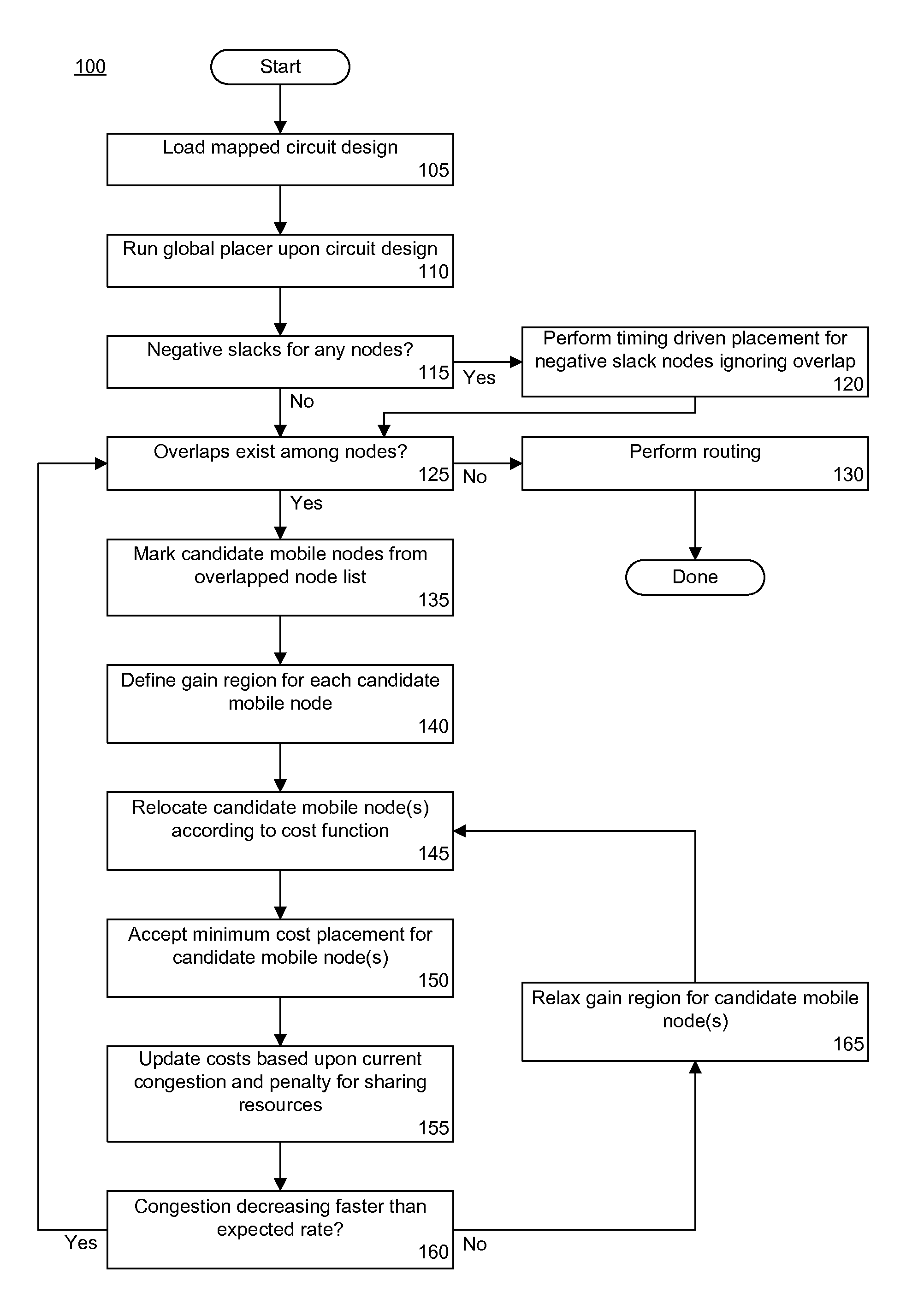
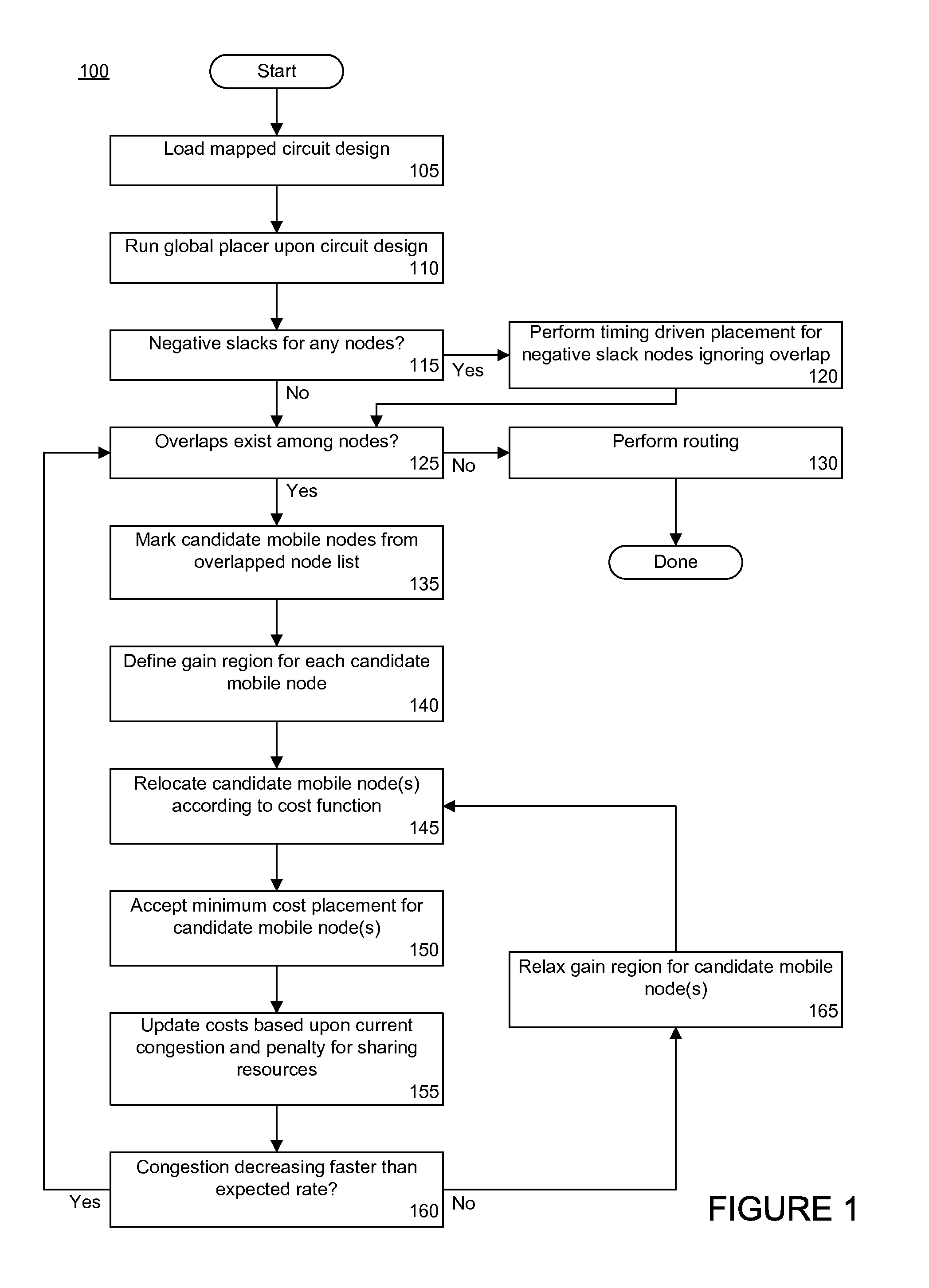
[0018]While the specification concludes with claims defining the features of the invention that are regarded as novel, it is believed that the invention will be better understood from a consideration of the description in conjunction with the drawings. As required, detailed embodiments of the present invention are disclosed herein; however, it is to be understood that the disclosed embodiments are merely exemplary of the invention, which can be embodied in various forms. Therefore, specific structural and functional details disclosed herein are not to be interpreted as limiting, but merely as a basis for the claims and as a representative basis for teaching one skilled in the art to variously employ the inventive arrangements in virtually any appropriately detailed structure. Further, the terms and phrases used herein are not intended to be limiting but rather to provide an understandable description of the invention.

[0019]The present invention provides a solution for producing a de...


PUM


Abstract

A method of placing a circuit design can include selecting one or more candidate mobile nodes from a plurality of overlapped nodes of the circuit design and determining a gain region for each candidate mobile node. The method also can include assigning the candidate mobile node to a site within a gain region according to a cost function. The gain region is associated with the candidate mobile node. The method further can include iteratively selecting and assigning candidate mobile nodes according to a measure of overlap for the circuit design.

Description

BACKGROUND[0001]1. Field of the Invention[0002]The present invention relates to the field of circuit design and, more particularly, to deriving a legal placement for a circuit design.[0003]2. Description of the Related Art[0004]One important task in the process of implementing a circuit design from a hardware description language (HDL), such as VHDL® or Verilog®, is placement. Placement refers to the process of assigning coordinate locations from an abstract grid representation of a particular target device, such as a programmable logic device (PLD), to various blocks and pins of the circuit design. The objective of placement is to assign locations such that signals linking the blocks and pins can be routed using minimal resources and / or meet established timing requirements.[0005]Before the circuit design can be placed, the circuit design is mapped. A PLD such as Field Programmable Gate Array (FPGA), for example, can include an assortment of different component types such as memorie...

Claims


Application Information

Patent Timeline
22 Dec 2009
Publication
US7636876B1
IPC
G01R31/28; G06F11/00; G06F17/50
CPC
G06F17/5072; G06F17/505; G06F30/327; G06F30/392
Inventors
SRINIVASAN, SANKARANARAYANAN; DASASATHYAN, SRINIVASAN