Detachable light assembly

a technology of detachable lights and locking mechanisms, which is applied in the direction of coupling device connections, transportation and packaging, lighting and heating apparatus, etc., can solve the problems of cumbersome prior art systems, loose contact of lighting systems, and inability to adjust the position of the light assembly, etc., to achieve enhanced locking mechanisms, eliminate the use of latch mechanisms, and facilitate the effect of engagement and re-engagemen

Inactive Publication Date: 2010-05-11
ADDARIO A
View PDF7 Cites 4 Cited by
  • Summary
  • Abstract
  • Description
  • Claims
  • Application Information

AI Technical Summary

Benefits of technology

[0014]It is further an object of the present improvement to provide a double locking means to withstand any type of driving conditions or unlimited times of launching and removal of the boat and trailer from the water.
[0015]It is further an object of the present improvement to provide an enhanced locking mechanism for attachment of the light assembly to the support assembly and still provide the ease and quickness for engagement and re-engagement to the boat trailer.

Problems solved by technology

The prior art systems provide a cumbersome means in attempt to produce the advantages of the present improved locking system.
After repeated use of said latch mechanism in engaging and disengaging the lamp assembly, the latch mechanism has a tendency to provide a less secure attachment increasing the likelihood of inadvertent detachment or resulting in loose contact of the lighting system during obverse driving conditions or repeated use over time.
In addition since the latch mechanism is mounted on either the lamp assembly or the support assembly it is exposed to come in contact with debris or any matter during travel that could cause inadvertent release of the latch mechanism resulting in complete loss of a light assembly or dysfunctional operation from loose contacts.

Method used


Image

  • Detachable light assembly
  • Detachable light assembly
  • Detachable light assembly

Examples


Embodiment Construction

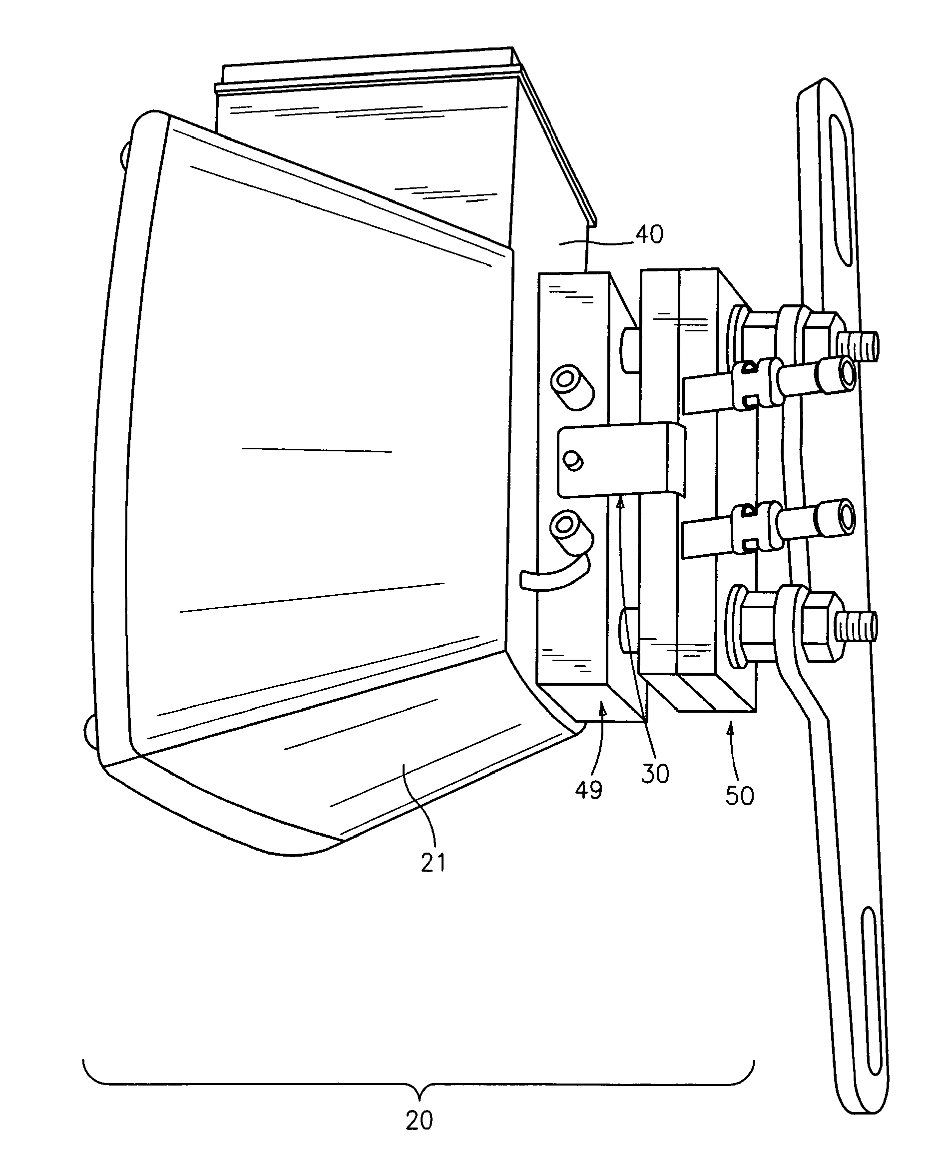
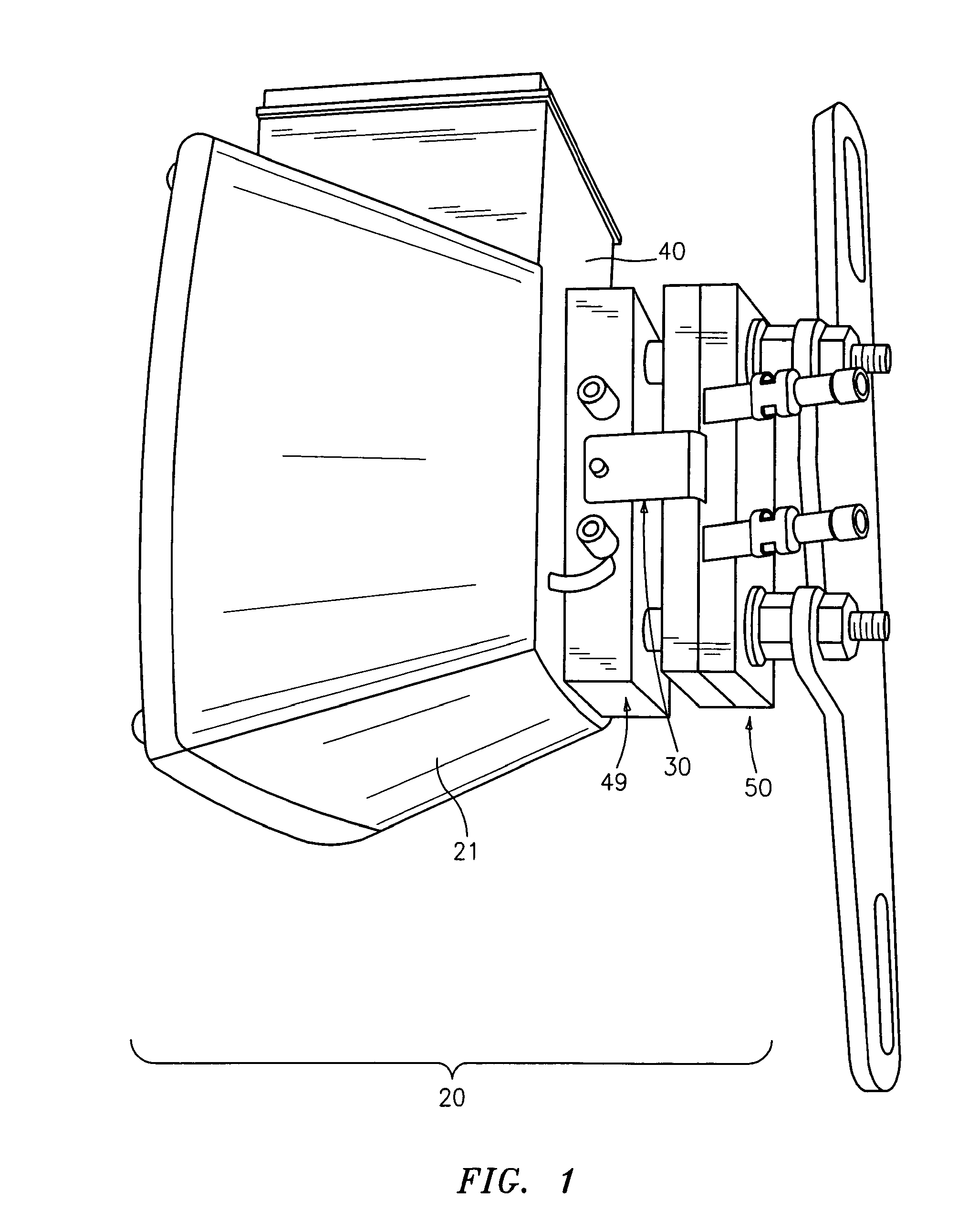
[0016]With reference now to the drawings, and in particular FIG. 1 thereof, the preferred embodiment of the detachable light system 20 in combination with the locking mechanism 30 of the present invention will be described.

[0017]A support assembly 50, attached to a vehicle by an attachment means is mated to a rectangular plate 49 by a plurality of connector plugs 41 in communication with a plurality of recessive channels 36 in support assembly 50. The rectangular plate 49 is attached to a light housing 21 to form the light assembly 40. The detachable light system 20 comprising of locking mechanism 30 engaging support assembly 50 with rectangular plate 49 is more specifically described in FIGS. 2, 3, 4&5.

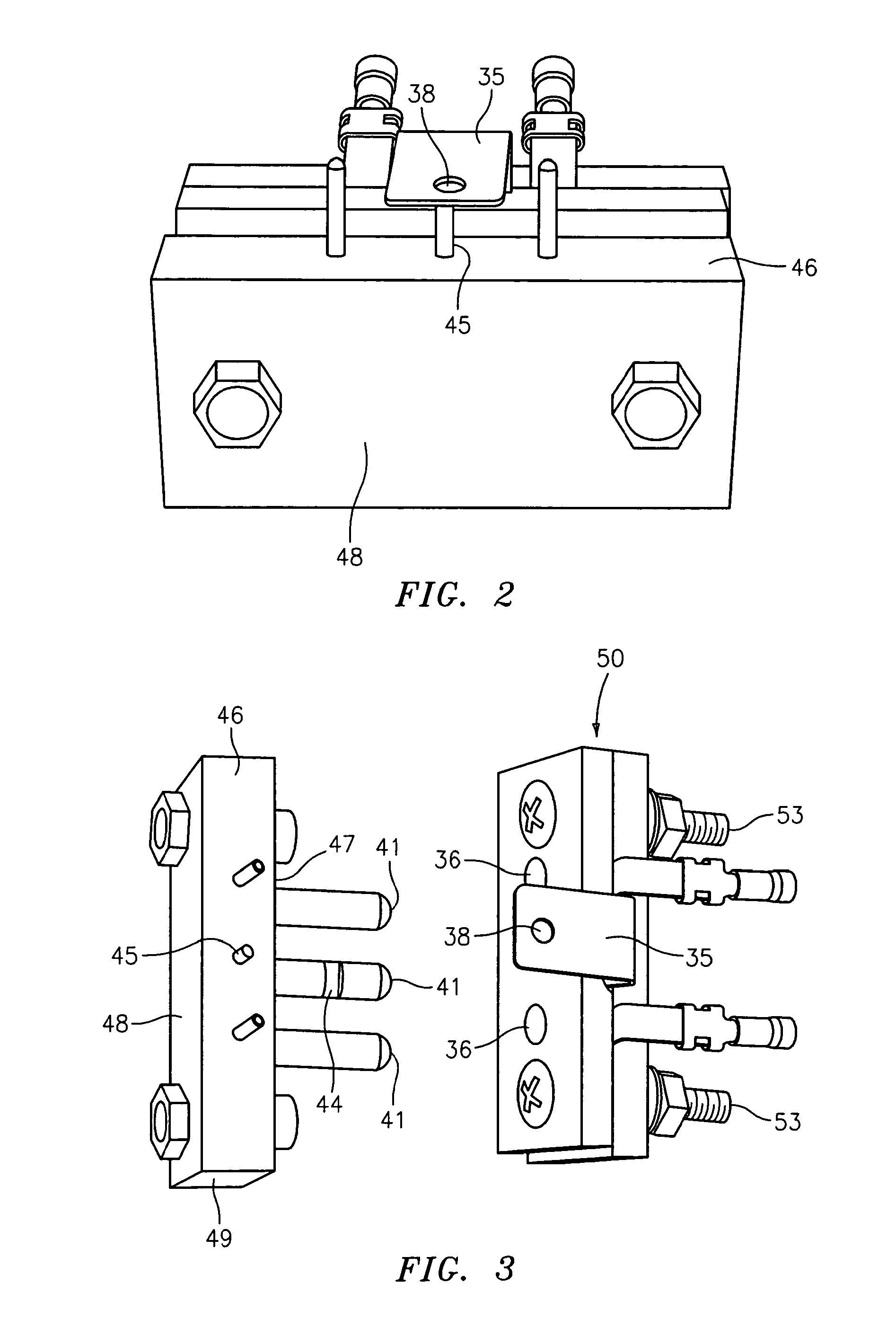
[0018]As illustrated in FIGS. 2, 3, 6&7 the locking mechanism consists of an L-shaped member 30 having a horizontally extending plate 35 with a hole 38 centrally positioned at a distal end of the horizontal plate 35. The L-shaped member further consisting of a downward depending sect...


PUM


Abstract

An improved multi-point locking mechanism in combination with a lamp assembly and a support assembly with mating, cooperating plug connectors providing a detachable lamp assembly for use on vehicles, such as boat trailers, for quick removal before exposure to corrosive water. The improved locking mechanism, in addition to providing a means for quick detachment and removal of the light assembly, provides a stronger and durable engagement with the support assembly preventing accidental dislodgement while towing vehicles, like boat trailers. The locking mechanism comprising a corrosive resistant L-shaped member having a horizontal extending plate with a hole through the distal end, and a downward depending section retractably positioned within the support assembly. In the engaged position, the L-shaped member being in a downward position, a receiving pin on the lamp assembly is mated with the support assembly by alignment with the hole in the horizontal plate and the depending section being in communication with a cut-out section in the cooperating plug connector providing the multi-point locking mechanism.

Description

BACKGROUND OF THE INVENTION[0001]1. Field of the Invention[0002]The present invention relates to an improved locking mechanism in combination with a detachable light system for use on vehicles, such as boat trailers and more particularly, pertains to a multi-point locking means providing quick and easy removal of trailer lights with respect to a boat trailer, quick engagement of the trailer lights and a durable locking means preventing inadvertent detachment when towing the vehicle.[0003]2. Description of the Prior Art[0004]A detachable light system for use on a boat trailer is highly desirable to eliminate exposure of the lighting system to corrosion from repeated launching of a boat from a boat trailer. The ease of quick and easy removal of trailer lights, in particular, and quick re-engagement is essential features of these devices. Of equal importance, a highly desirable feature is a device that provides improved durability and security eliminating the inadvertent dislodgment of...

Claims


Application Information

Patent Timeline
Patent Type & Authority Patents(United States)
IPC IPC(8): H01R33/00
CPCB60Q1/305B60Q1/0088
Inventor ADDARIO, ALDO
Owner ADDARIO A
Why Eureka
Try Eureka