Useful energy product

a technology of energy products and energy products, applied in the direction of energy-based chemical/physical/physical-chemical processes, chemical/physical processes, refining by electric/magnetic means, etc., can solve the problems of limited above-effects and the inability of the susceptor's structure to allow the applied energy to penetrate into the entire volume, etc., to reduce the cost of operating such a device, reduce the cost of operation, and reduce the effect of efficiencies

Inactive Publication Date: 2010-05-11
DALTON ROBERT
View PDF3 Cites 31 Cited by
  • Summary
  • Abstract
  • Description
  • Claims
  • Application Information

AI Technical Summary

Benefits of technology

[0028]The depth of penetration of susceptor must allow for applied UV energy to penetrate the susceptor for volumetric interaction a) with the susceptor to produce fluorescent radiation and / or b) directly between the applied UV energy and gaseous / particulate species. Consequently, if UV and microwave energies are applied to the same susceptor, other interactions may occur between the applied energies, material of construction of the susceptor, field concentrators and the gaseous species (or particulate). The UV energy that is applied to the cavity can interact as previously mentioned, however the microwave energy a) may produce thermoluminescence in the phosphorescent materials b) may produce heat in the susceptor by the applied microwave energy and / or c) may enhance the phosphorescent radiation produce primarily by the applied UV energy. Of other consequence, if the applied energy to the same susceptor is only microwave energy then other interactions may occur. The microwave energy either a) may be completely absorbed for thermal treatment of the chemical species, b) may be partially absorbed and interact with the chemical species for interaction, c) may be used to heat the susceptor and produce thermophosphorescence of UV radiation, which interacts with the chemical species, or d) a combination of the mentioned interactions in a, b, and c.
[0074]Another embodiment of this invention is a heat transfer process. The invention embodies the input chemical species flow obtaining heat, or being preheated, prior to entering the device for thermal or other methods of treatment by a heat exchange method that provides heat to the input chemical species flow from heat that is produced from the source for applied energy. The source can be any device that produces the applied energy. Such a device generally operates at low efficiencies and produces heat. This heat transfer process for preheating the input chemical species flow will decrease the cost of operating such a device. The heat from the tube, or tubes, can be exchanged with the input chemical species flow. After the input chemical species flow is preheated with heat from the tube, the input chemical species flow can be further heated by heat transfer either a) from the cavity walls, b) from a conventional heat exchanger (a recuperator) which is located after the exit end of the device, or c) from both the cavity walls and conventional recuperator.

Problems solved by technology

However, these above effects are limited and influenced by the size, shape, conductivity and volume fraction of the material embedded in a matrix of low dielectric loss, low dielectric constant of the material as well as the wavelength of the incident radiation.
If so, the susceptor's structure will not allow for the applied energy to penetrate into the entire volume of Sic granules.

Method used


Image

  • Useful energy product
  • Useful energy product
  • Useful energy product

Examples


Embodiment Construction

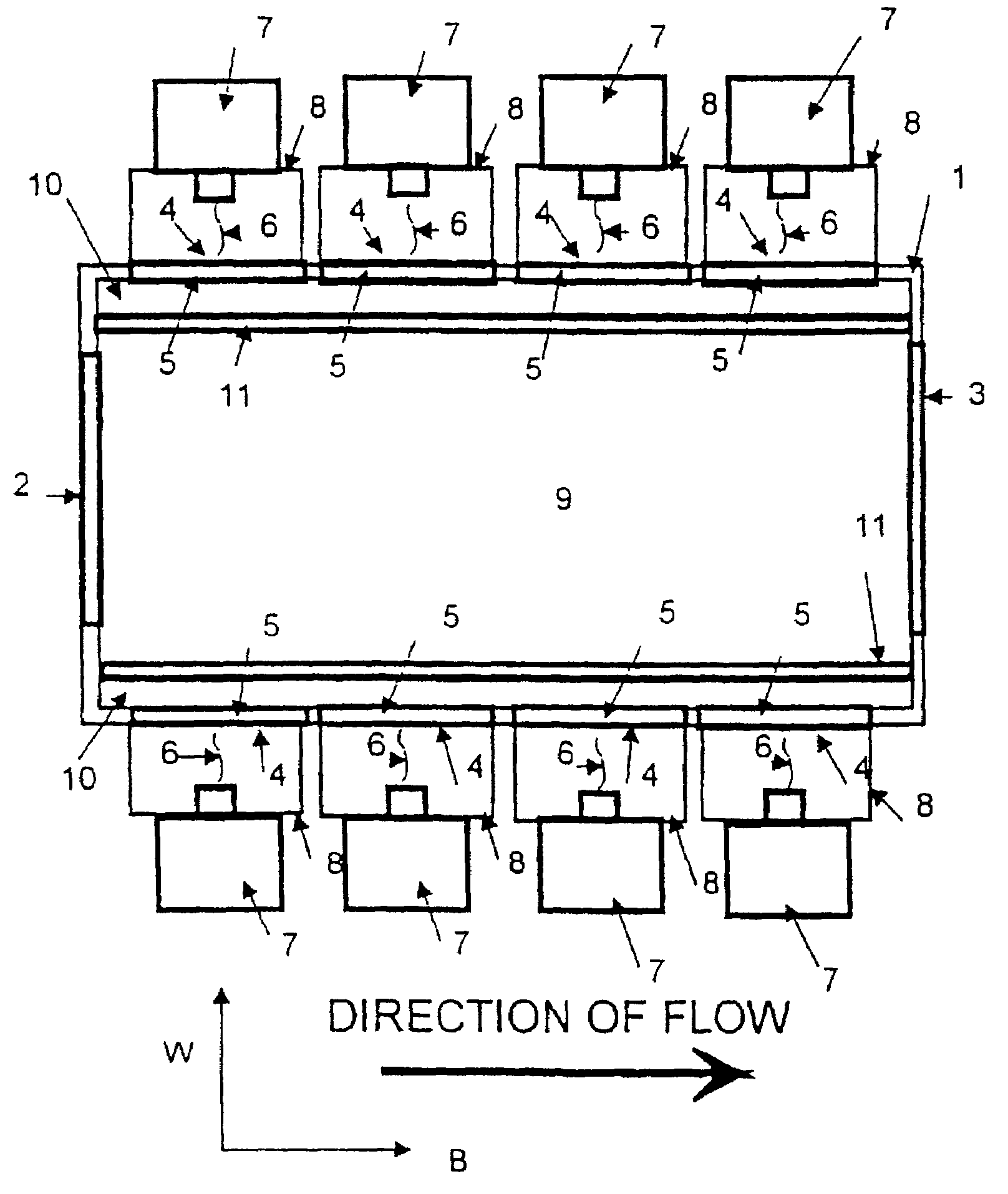
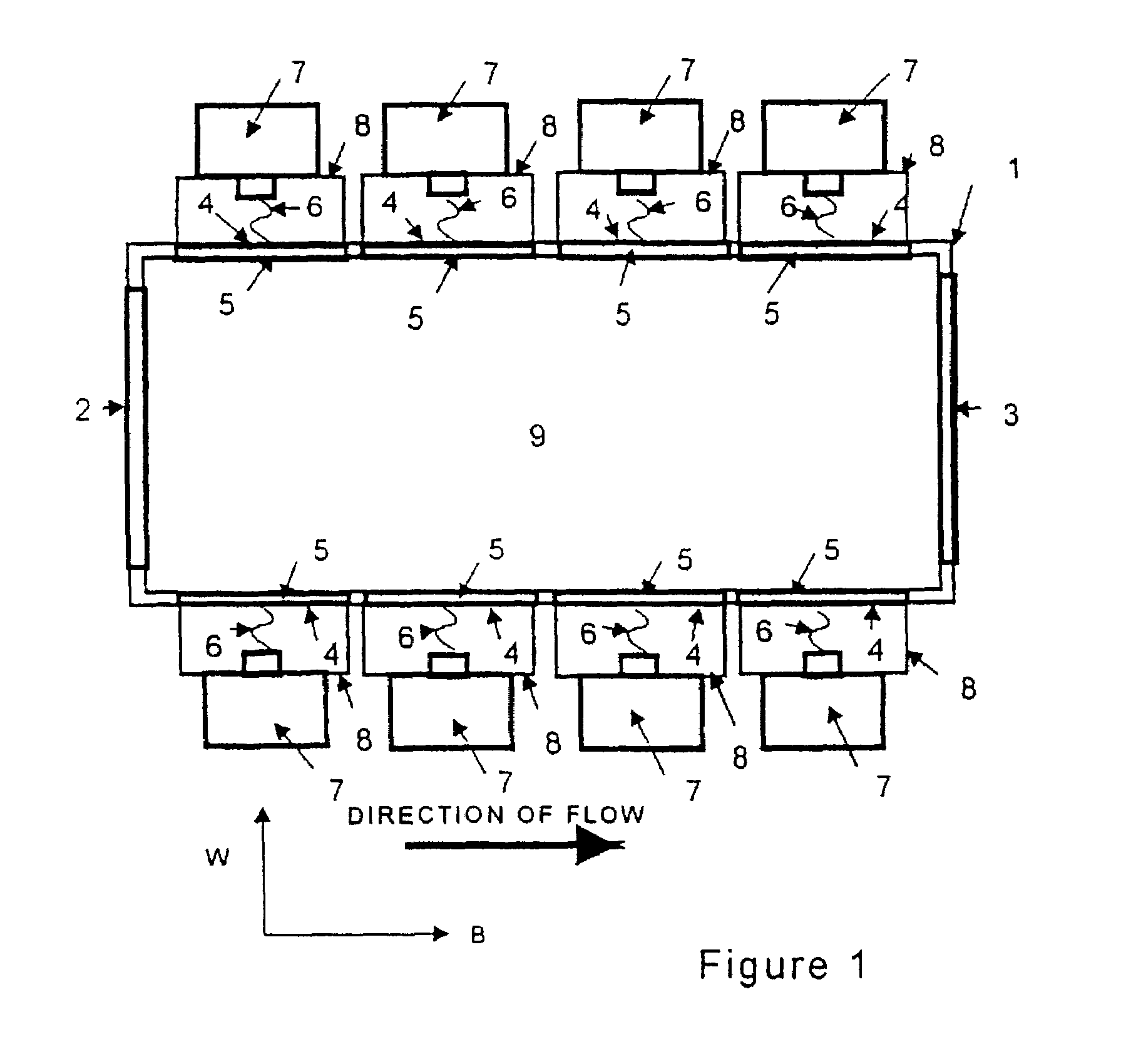
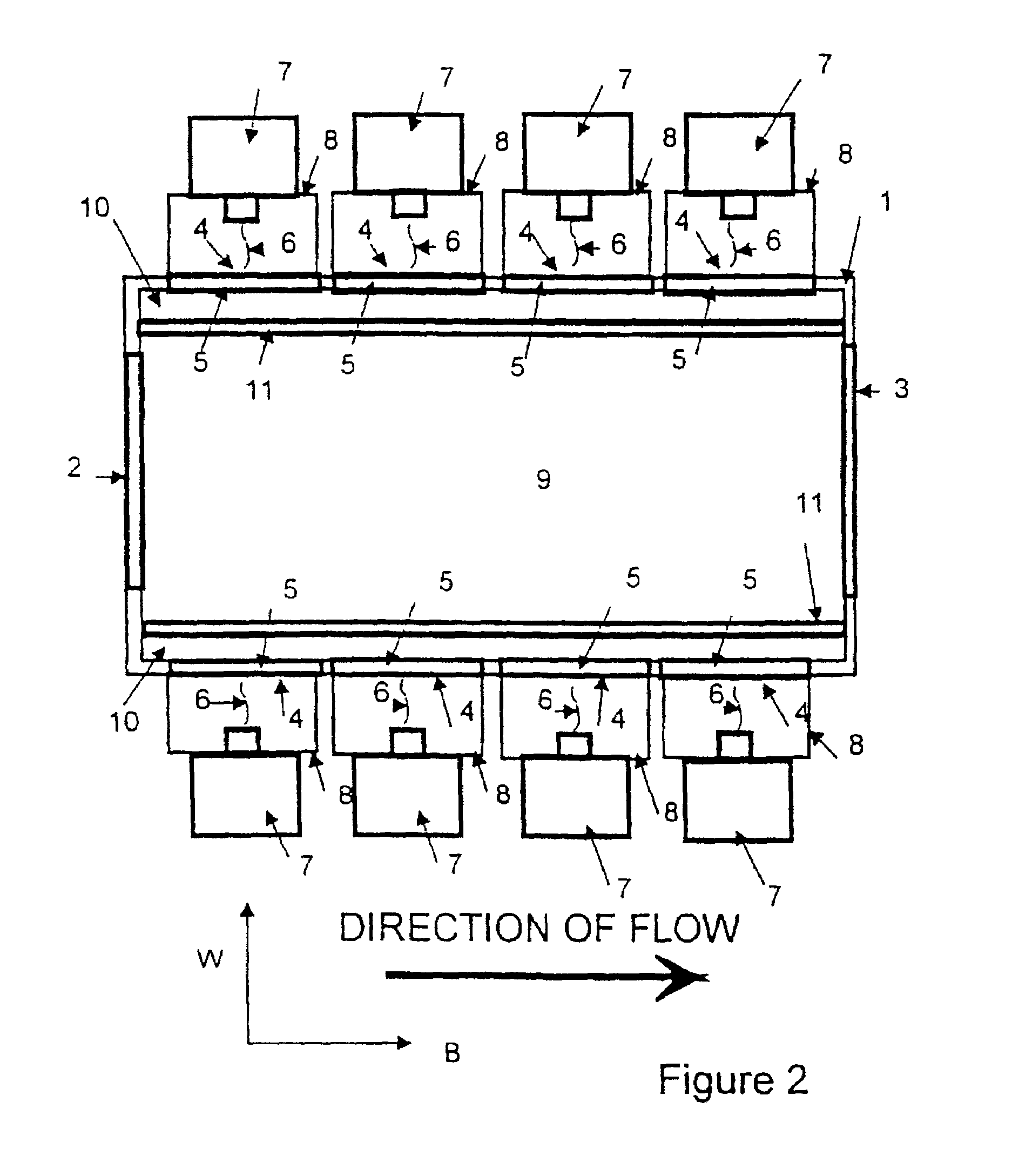
[0084]This invention is a useful energy product created by a process where a chemical species flow passes through a macroscopic artificial dielectric structure for a gas-permeable susceptor consisting of first regions in the structure that are primarily transparent to applied electromagnetic energy and second regions in the structure that are not primarily transparent to applied electromagnetic energy. This invention is a device that uses a gas-permeable structure for a susceptor of electromagnetic energy to react gases for desired products. The device has a specific cavity geometry, location where the applied energy from a source enters the cavity, a susceptor that is designed by the depth of penetration of the susceptor, and a means to scale-up the device for larger flow rates of an air stream without changing the susceptor's interaction with the applied energy or depth of penetration of the susceptor because the device is designed to increase the size of the device by a near line...


PUM

PropertyMeasurementUnit
thicknessaaaaaaaaaa
thicknessaaaaaaaaaa
diameteraaaaaaaaaa

Abstract

A useful energy product created by a process where a chemical species flow passes through a macroscopic artificial dielectric structure for a gas-permeable susceptor having (a) first regions in the structure that are primarily transparent to applied electromagnetic energy and (b) second regions in the structure that are not primarily transparent to applied electromagnetic energy.

Description

CROSS-REFERENCE TO RELATED APPLICATIONS[0001]The present application is a continuation-in-part or U.S. patent application Ser. No. 10 / 351,768, filed on 27 Jan. 2003, allowed and which will issue as U.S. Pat. No. 7,176,427 on 13 Feb. 2007, which is a continuation-in-part of U.S. patent application Ser. No. 09 / 897,268, filed on 2 Jul. 2001, which issued as U.S. Pat. No. 6,512,215 on 28 Jan. 2003, which is a divisional of U.S. patent application Ser. No. 09 / 402,240, filed on 29 Sep. 1999, which issued as U.S. Pat. No. 6,271,509 B1 on 7 Aug. 2001, which is the US National Phase under Chapter II of the PCT of PCT Patent Application No. PCT / US98 / 06647, which published as International Publication No. WO 98 / 46046 on 15 Oct. 1998, which claims the benefit of U.S. Provisional Patent Application No. 60 / 041,942, filed on 4 Apr. 1997, all of which are incorporated herein by this reference.BACKGROUND OF THE INVENTION[0002]1. Field of Invention[0003]This invention relates to a useful energy produ...

Claims


Application Information

Patent Timeline
Patent Type & Authority Patents(United States)
IPC IPC(8): H05B6/64
CPCB01J19/02C01B3/24C01B13/10C04B33/04C04B35/01C04B35/18C04B35/44C04B35/50C04B35/581C10G3/00C10G15/08C10G32/02H05B6/802B01J19/12C10G2300/1018B01J2219/00141B01J2219/00146B01J2219/00155B01J2219/0218B01J2219/182B01J2219/185B01J2219/192B01J2219/1923C01B2201/84C01B2203/0855C04B2235/3203C04B2235/3206C04B2235/3208C04B2235/3213C04B2235/3222C04B2235/3224C04B2235/3227C04B2235/3232C04B2235/3236C04B2235/3243C04B2235/3272C04B2235/3826C04B2235/3865C04B2235/80H05B2206/044C10G2300/1037C10G2300/1014Y02P30/20
Inventor DALTON, ROBERT
Owner DALTON ROBERT
Why Eureka
Try Eureka