Electronic device

a technology of electronic devices and contacts, applied in the direction of coupling device connections, fixed connections, electrical apparatus casings/cabinets/drawers, etc., can solve the problems of high error rate in the production of such control units, electrical breakdowns, etc., and achieve the effect of reliably preventing contacts from becoming loos

a technology of electronic devices and contacts, applied in the direction of coupling device connections, fixed connections, electrical apparatus casings/cabinets/drawers, etc., can solve the problems of high error rate in the production of such control units, electrical breakdowns, etc., and achieve the effect of reliably preventing contacts from becoming loos

US7722405B2Inactive Publication Date: 2010-05-25CONTINENTAL AUTOMOTIVE GMBH

Image

  • Electronic device
  • Electronic device
  • Electronic device

Examples


Embodiment Construction

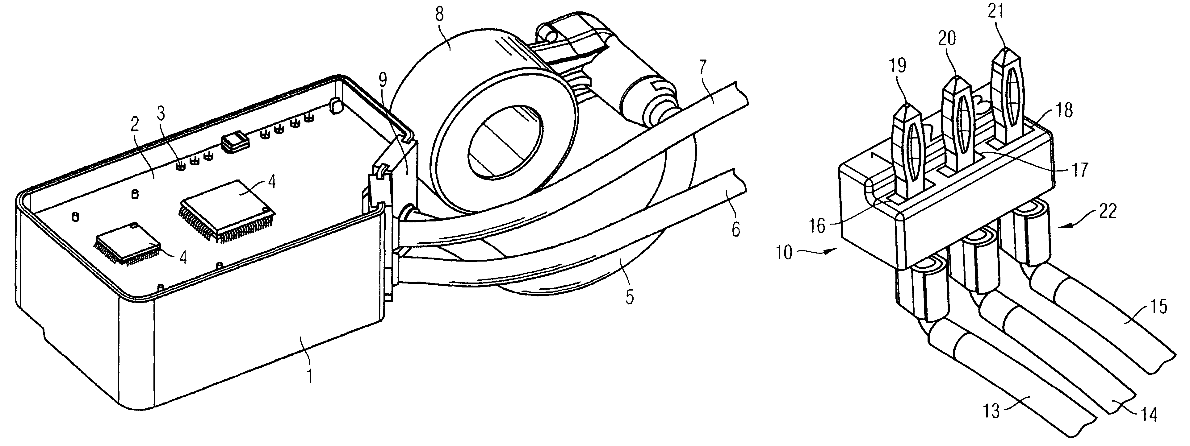
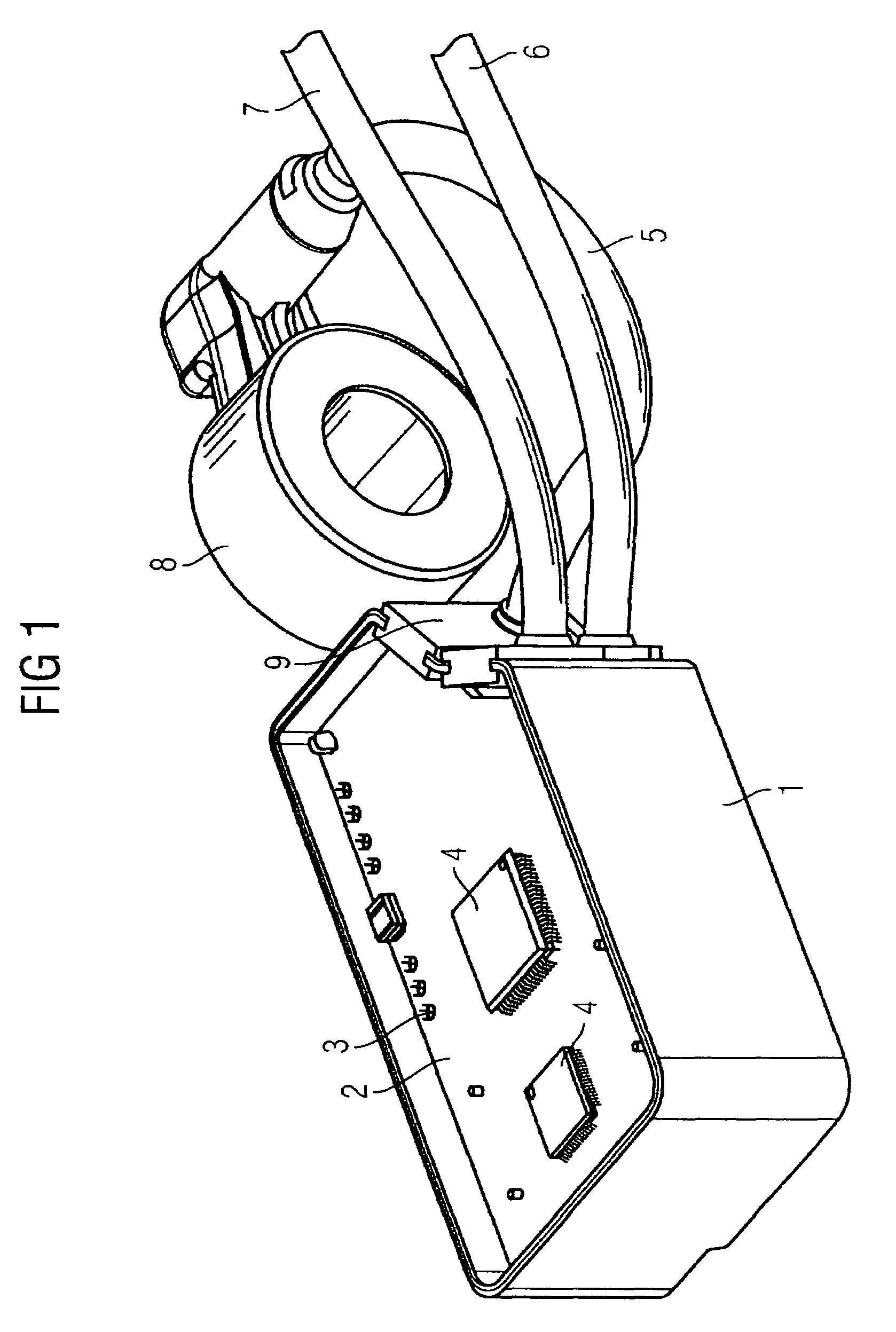
[0022]FIG. 1 illustrates a control unit for use on the shock absorbers of a motor vehicle, which control unit regulates the flow of hydraulic liquid through a valve. The control unit has an integral pot-like housing 1 which is composed of plastic and is produced as an injection-molded part. The housing 1 is covered by a printed circuit board 2 which supports electrical components 4 which contain the regulation means for the shock absorber valve. The connection wires of the cables 5, 6, 7 which electrically connect the control unit to the surroundings extend through the contact openings 3 in the printed circuit board 2. In this case, the line 5 is connected to a coil 8 which serves for inductive energy transfer of the valve (not illustrated any further). On one side, the housing 1 has seals 9 which are each pushed over a cable 5, 6, 7 and at the same time are inserted into the housing wall as part of the housing wall arrangement.

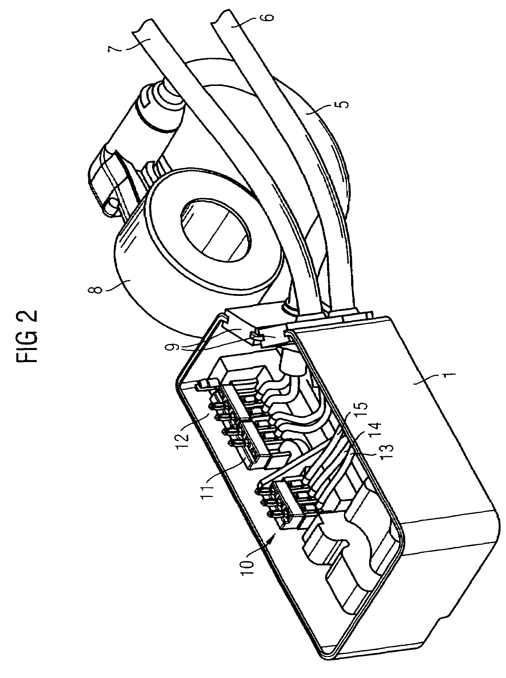
[0023]In FIG. 2, the housing 1 is illustrated without t...


PUM


Abstract

The invention relates to an electronic device with a housing to accommodate a support substrate, provided with an electronic circuit, whereby the electronic circuit makes contact with at least one electrical line, leading out of the housing. The electrical line is connected to a rigid contact element on a contact holder and the contact element is introduced into the support substrate to make contact with the electronic circuit.

Description

CROSS REFERENCE TO RELATED APPLICATIONS[0001]This is a U.S. national stage of application No. PCT / EP2005 / 0552367, filed on 14 Oct. 2005. Priority is claimed on DE 10 2004 057 404.9, filed 26 Nov. 2004 and DE 10 2004 060 694.3, filed 16 Dec. 2004, the contents of which are incorporated here by reference.BACKGROUND OF THE INVENTION[0002]1. Field of the Invention[0003]The invention relates to an electronic device having a housing for accommodating a support substrate which supports an electronic circuit, with at least one electrical line, which is routed out of the housing, making contact with the electronic circuit.[0004]2. Description of the Prior Art[0005]In motor-vehicle electronics, the electronic circuits for controlling individual vehicle functions are arranged on a printed circuit board which is arranged in a housing directly at the location of the actuating drive to be controlled. In this case, the electronic circuit is connected to the vehicle-body side by means of cables. Th...

Claims


Application Information

Patent Timeline
25 May 2010
Publication
US7722405B2
IPC
H01R25/00; H01R12/55; H01R12/58
CPC
H05K5/0247; H05K5/0069
Inventors
JAKLIN, RALF; ULLRICH, HORST