Polarization linkage of high dielectric constant pivoted planar solar concentrator mirrors

a technology of solar concentrator mirrors and dielectric constants, applied in the field of solar energy concentrator fresnel reflector arrays, can solve the problems of no prior art found, and achieve the effects of reducing latching force, simple and efficient alignment, and improving stability

Inactive Publication Date: 2010-06-15
RABINOWITZ MARIO
View PDF22 Cites 17 Cited by
  • Summary
  • Abstract
  • Description
  • Claims
  • Application Information

AI Technical Summary

Benefits of technology

[0044]In the Induced High Dielectric Constant Dipole Alignment Adjustable Fresnel Planar Mirror Solar Concentrators that have been developed, the rotatable optical elements (mirrors) can be aligned to concentrate solar energy on a receiver having dimensions small compared to the dimensions of the array. This permits the focal point of the array to remain focused on the receiver over the course of a day and throughout the year. The swivel point for rotation is located above the mirrors, giving the additional advantage of vertical stability. Vertical stability provides a natural fiducial or starting point, as well as enabling simpler and more efficient alignment. At startup for initial operation, or following a blackout, having the swivel point affixed above the mirrors gives them a natural quasi-vertical position since the center of mass of the mirrors is below the swivel suspension point. A given natural angle with respect to the vertical can be built in to the mirrors by weight distribution and / or constructing the mirrors with a cocked angle relative to their support stem. Such quasi-vertical positioning allows the mirrors to start from a nearly aligned position, rather than having to move over a much larger angle for alignment. Furthermore, the natural stability of a quasi-vertical position [as opposed to the natural stability of a quasi-horizontal position when the swivel point is below the mirrors] permits a substantial reduction in the latching force required to hold the mirrors in alignment between alignment operations.
[0045]Receivers, such as photovoltaic cells, convert the solar energy focused and delivered to them by the solar concentrator directly into electrical energy or via heat engines (e.g. Stirling cycle engines) which convert the solar energy into mechanical energy which can be used directly, or indirectly converted to electricity. This invention provides an increased force positioning system by means of high dielectric materials, to overcome friction and to allow for the use of smaller positioning electric fields.

Problems solved by technology

No prior art was found that utilized induced dipole alignment in electric fields of swiveled mirrors that are vertically stable in a Fresnel reflector solar concentrator, optical switches, displays, or other similar equipment.

Method used


Image

  • Polarization linkage of high dielectric constant pivoted planar solar concentrator mirrors
  • Polarization linkage of high dielectric constant pivoted planar solar concentrator mirrors
  • Polarization linkage of high dielectric constant pivoted planar solar concentrator mirrors

Examples


Embodiment Construction

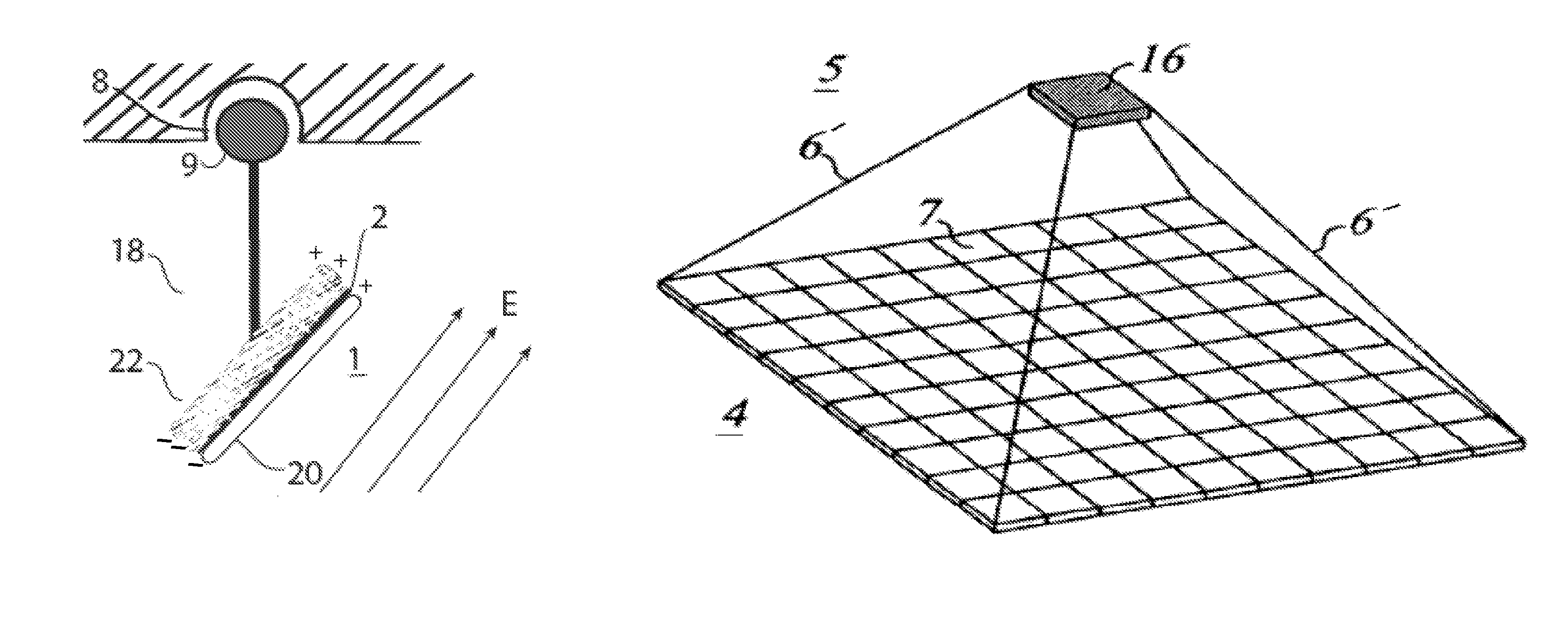
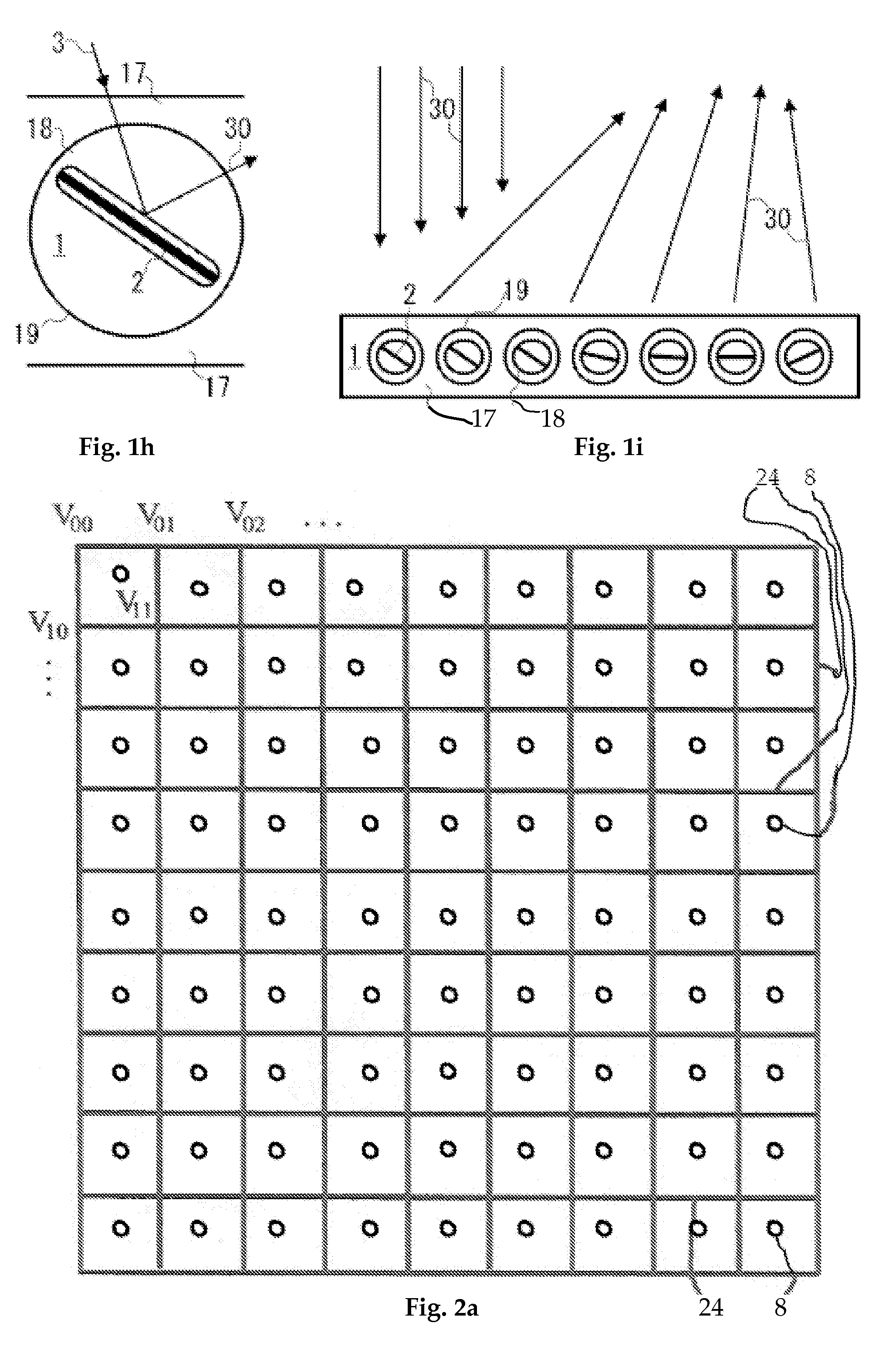
[0110]As is described here in detail, the objectives of the instant invention may be accomplished by any of a number of ways separately or in combination, as taught by the instant invention. A tracking solar concentrator has been developed in which the orientation of individual optical elements (mirrors, reflectors, lenses) is accomplished by electric dipole interaction between the electric field of a grid and an induced dipole, and / or an electret dipole, to align them consecutively or concurrently without the need for expensive, bulky, and heavy motors. Thus the improved solar concentrator of the instant invention can be less expensive, more reliable, and lighter in weight than conventional solar arrays.

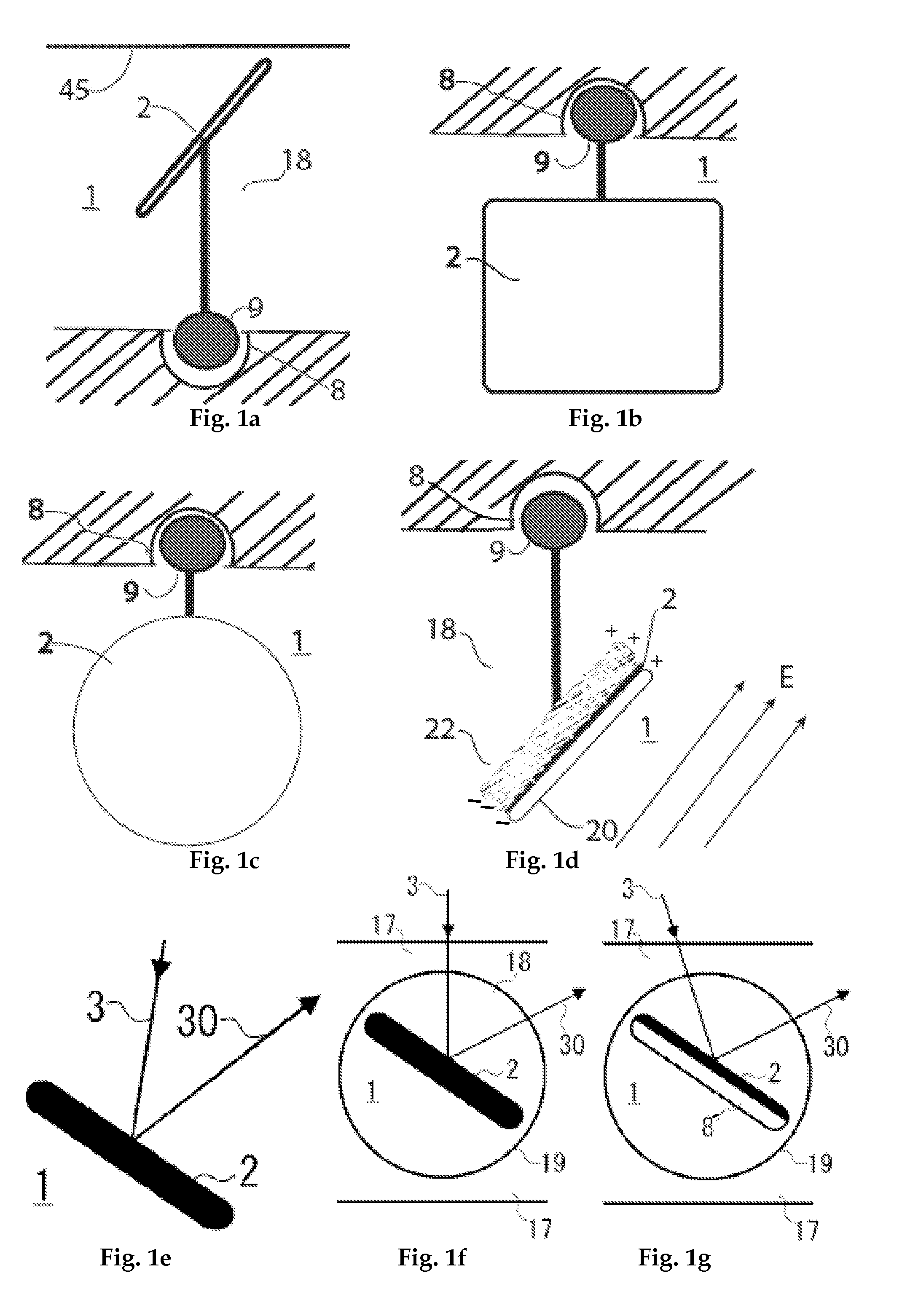
[0111]FIG. 1a is a cross-sectional side view of a mirror 2 supported underneath by a universal swivel (pivot) 9 that is in a supporting swivel bearing 8, as one optical element 1 of an adjustable Fresnel reflector solar concentrator. The element 1 is immersed in a transparent dielec...


PUM


Abstract

A highly polarizable high dielectric constant positioning and motion control of the elements (approximately planar mirrors) of a Fresnel reflector solar concentrator tracking heliostat array wherein the elements are suspended with the center of mass above the swivel point, below the swivel point, or have an internal-swivel. The torque to produce angular deflection, and rotational motion is provided by induced and / or permanent dipole coupling to an electronic grid. The force interaction is greatly enhanced by securing a high dielectric material adjacent to each mirror. Thus forces and torques are produced without the use of motors. This allows maximization of solar energy focused by a low-profile concentrator array onto a receiver. Dynamic motion can be controlled over a wide range of dimensions from nanometers to decimeters.

Description

FIELD OF THE INVENTION[0001]The instant invention relates generally to a Solar Energy Concentrator Fresnel reflector array that tracks the sun and focuses reflected light by means of greatly augmented induced dielectric dipole alignment of pivoted mirrors. The mirrors may be on a universal pivot that can rotate or tilt in any direction; or on gimbal pivots. By utilization of a high dielectric constant material attached to each mirror, the polarization linkage of the mirror to the alignment grid is greatly increased.BACKGROUND OF THE INVENTION[0002]This invention provides a better means to achieve affordable solar energy than by a conventional tracking heliostat array. In the latter, enabling the optical elements (mirrors) to be movable generally requires many large heavy motors that consume a great deal of power. This results in an expensive, bulky, and ponderous heliostat that is unfavorable for rooftop and other applications where much weight cannot be tolerated. The present inven...

Claims


Application Information

Patent Timeline
Patent Type & Authority Patents(United States)
IPC IPC(8): G02B5/10F24J2/38G02B7/182G03B21/00F24S50/20
CPCF24J2/16F24J2/5431G02B26/085F24J2/14F24J2002/1066Y02E10/47F24J2002/5437F24J2002/5489F24J2002/108F24S23/74F24S23/77F24S30/48F24S2023/85F24S2023/872F24S2030/11F24S2030/17
Inventor RABINOWITZ, MARIO
Owner RABINOWITZ MARIO
Why Eureka
Try Eureka