Thermal insulation for a building

a technology for building insulation and thermal insulation, applied in building roofs, transportation and packaging, layered products, etc., can solve the problems of less than desirable insulation properties of ceilings and roof systems

Inactive Publication Date: 2010-10-26
ELLIS BILLY
View PDF56 Cites 50 Cited by
  • Summary
  • Abstract
  • Description
  • Claims
  • Application Information

AI Technical Summary

Problems solved by technology

However, such ceiling and roof systems can have less than desirable insulation properties.

Method used


Image

  • Thermal insulation for a building
  • Thermal insulation for a building
  • Thermal insulation for a building

Examples


Embodiment Construction

[0019]Although the following detailed description contains many specific details for purposes of illustration, one having ordinary skill in the art will appreciate that many variations and alterations to the following details are within the scope of the invention. Accordingly, the exemplary embodiment of the invention described below is set forth without any loss of generality to, and without imposing limitations thereon, the claimed invention.

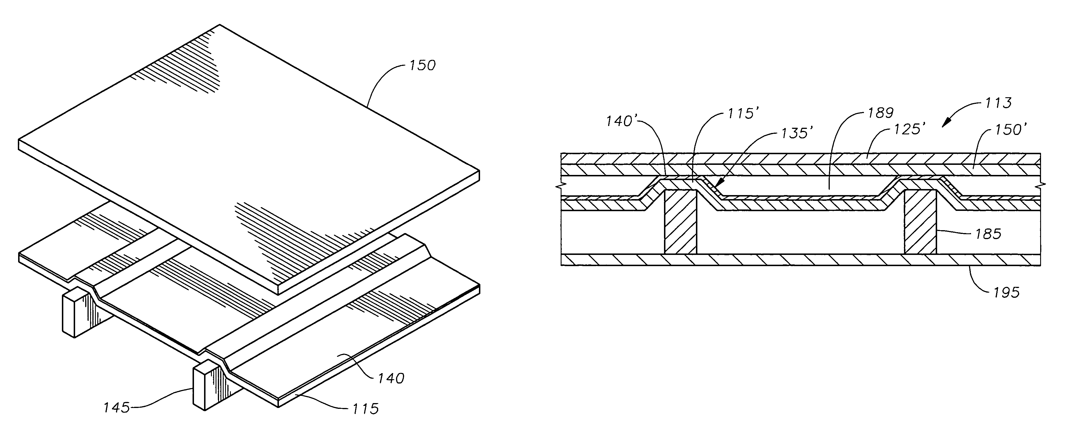
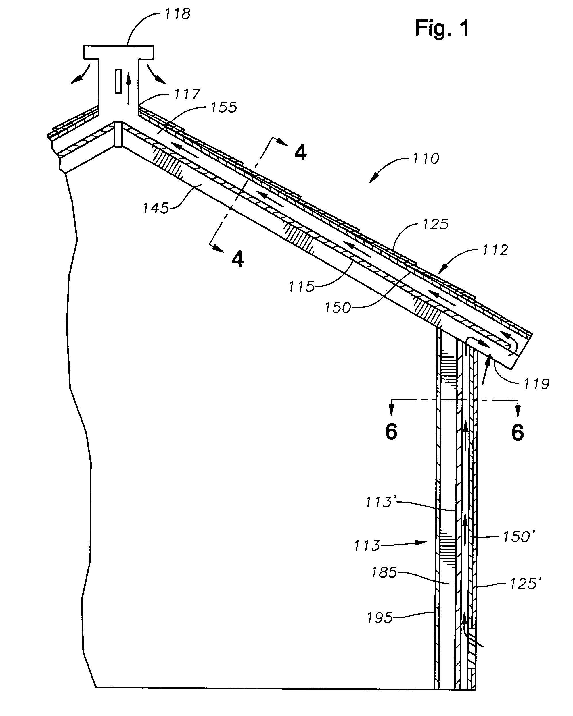
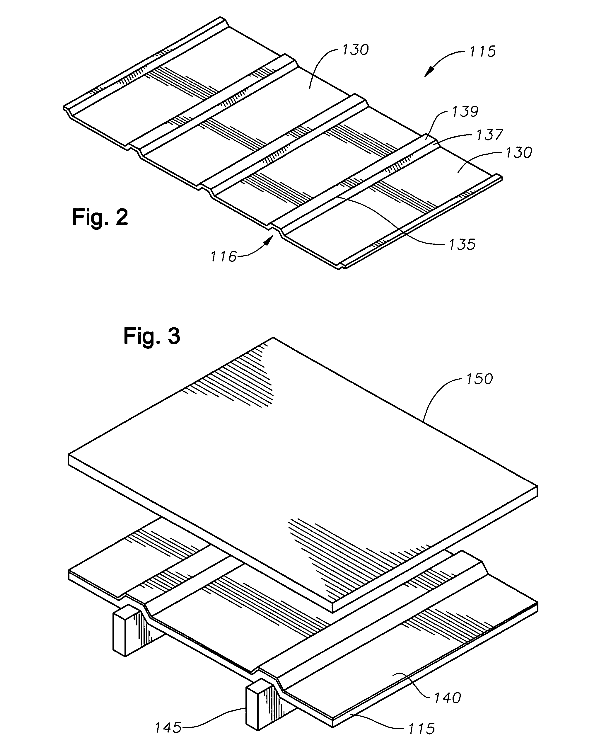
[0020]Referring to FIG. 1, an insulator or insulation panel 115 can be installed on part of a conventional roof 112 of a building 110. Insulation panel 115 extends from a top portion 117 of a roof 112 to a bottom soffit portion 119. Soffit portion 119 is a conventional structure that encloses the edge portions of roof 112. A conventional external surface element 125, such as shingles, can be installed on a top portion of roof 112 on top of plywood decking or panel 150 to interface environmental elements external to building 110. Insulation pan...


PUM

PropertyMeasurementUnit
lengthaaaaaaaaaa
lengthaaaaaaaaaa
thicknessaaaaaaaaaa

Abstract

An insulation system of a building having a plurality of spaced-apart support members has an insulator with a plurality of ribs are formed thereon. A concave portion of each rib receives one of the support members. A panel covers, and is secured to the support members. An exterior covering element is secured to an exterior side of the panel. A radiant heat barrier is bonded between the insulator and the panel. The insulator defines air ventilation channels between the foam insulator and the panel for venting air from building. An insulator assembly for a building has a sheet of foam insulation with a plurality of channels intermittently formed in the sheet of insulation. Each channel has a concave side and a convex side. The concave side is adapted to receive a support member of the building. A radiant heat barrier is bonded to a surface of the foam insulation.

Description

RELATED APPLICATIONS[0001]This nonprovisional patent application claims the benefit of co-pending, provisional patent application U.S. Ser. No. 60 / 667,395, filed on Apr. 1, 2005, which is hereby incorporated by reference in its entirety.BACKGROUND OF THE INVENTION[0002]1. Field of the Invention[0003]The invention relates generally to insulation for a building, and more particularly to insulated roof decking and wall insulation for the purpose of insulating the inside of a building from elements external to the building.[0004]2. Background of the Art[0005]The roof system of a conventional building generally includes uniformly spaced joists spanning the length between pairs of parallel support joists, where the joists form the ceiling. Wallboard and 2×6 boards can be placed on top of the uniformly spaced joists. Metal or wood trusses are then erected above the joists to form the framing for the roof. Exterior plywood sheathing is applied on top of the trusses and an exterior covering,...

Claims


Application Information

Patent Timeline
Patent Type & Authority Patents(United States)
IPC IPC(8): E04B7/00B32B3/30
CPCE04D13/1618E04D13/1637E04D13/17Y10T428/2457Y10T428/24496Y10T428/24694Y10T428/24999
Inventor ELLIS, BILLY
Owner ELLIS BILLY
Why Eureka
Try Eureka