Prosthetic foot with longer upper forefoot and shorter lower forefoot

a prosthetic foot and foot technology, applied in the field of foot prosthetic devices, can solve the problems of limited material and imagination, and achieve the effect of less resistance and more resistan

Inactive Publication Date: 2010-11-02
FREEDOM INNOVATIONS INC
View PDF179 Cites 26 Cited by
  • Summary
  • Abstract
  • Description
  • Claims
  • Application Information

AI Technical Summary

Benefits of technology

[0008]It has been recognized that it would be advantageous to develop a method and device for providing multiple energy storage elements in a prosthetic foot that are independently or corroboratively engageable to provide differing resistive energy to a user during stepping motions and standing positions. It has also been recognized that it would be advantageous to develop a prosthetic foot device that can provide more resistance during high load portions of a user's gait and less resistance when in a terminal stance.

Problems solved by technology

With respect to prosthetic feet, the development of a functional and natural artificial foot has been limited only by material and imagination.
Unfortunately, such multiple spring feet have not provided the stiff resiliency desired through high load portions of a user's gait while still allowing the foot to have a softer resiliency when the user assumes a terminal stance.

Method used


Image

  • Prosthetic foot with longer upper forefoot and shorter lower forefoot
  • Prosthetic foot with longer upper forefoot and shorter lower forefoot
  • Prosthetic foot with longer upper forefoot and shorter lower forefoot

Examples


Embodiment Construction

[0020]Reference will now be made to the exemplary embodiments illustrated in the drawings, and specific language will be used herein to describe the same. It will nevertheless be understood that no limitation of the scope of the invention is thereby intended. Alterations and further modifications of the inventive features illustrated herein, and additional applications of the principles of the inventions as illustrated herein, which would occur to one skilled in the relevant art and having possession of this disclosure, are to be considered within the scope of the invention.

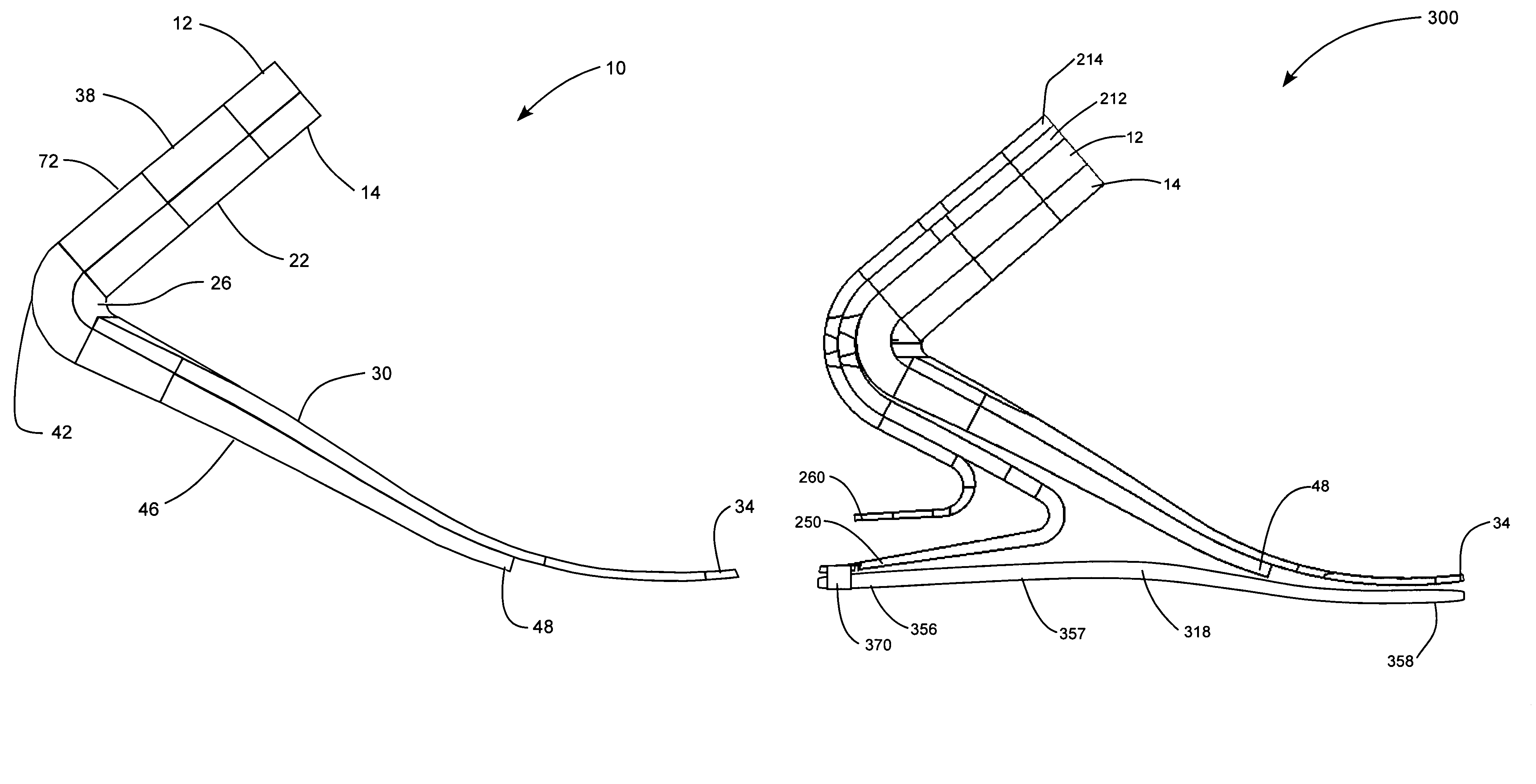
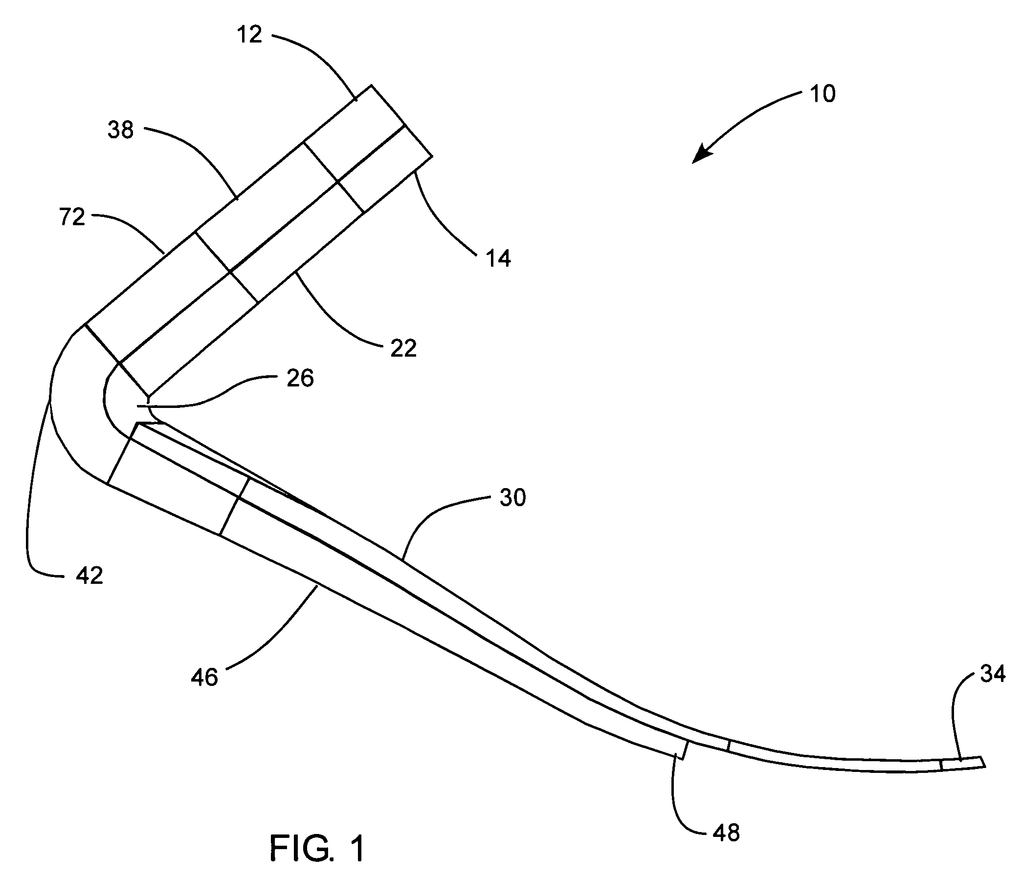
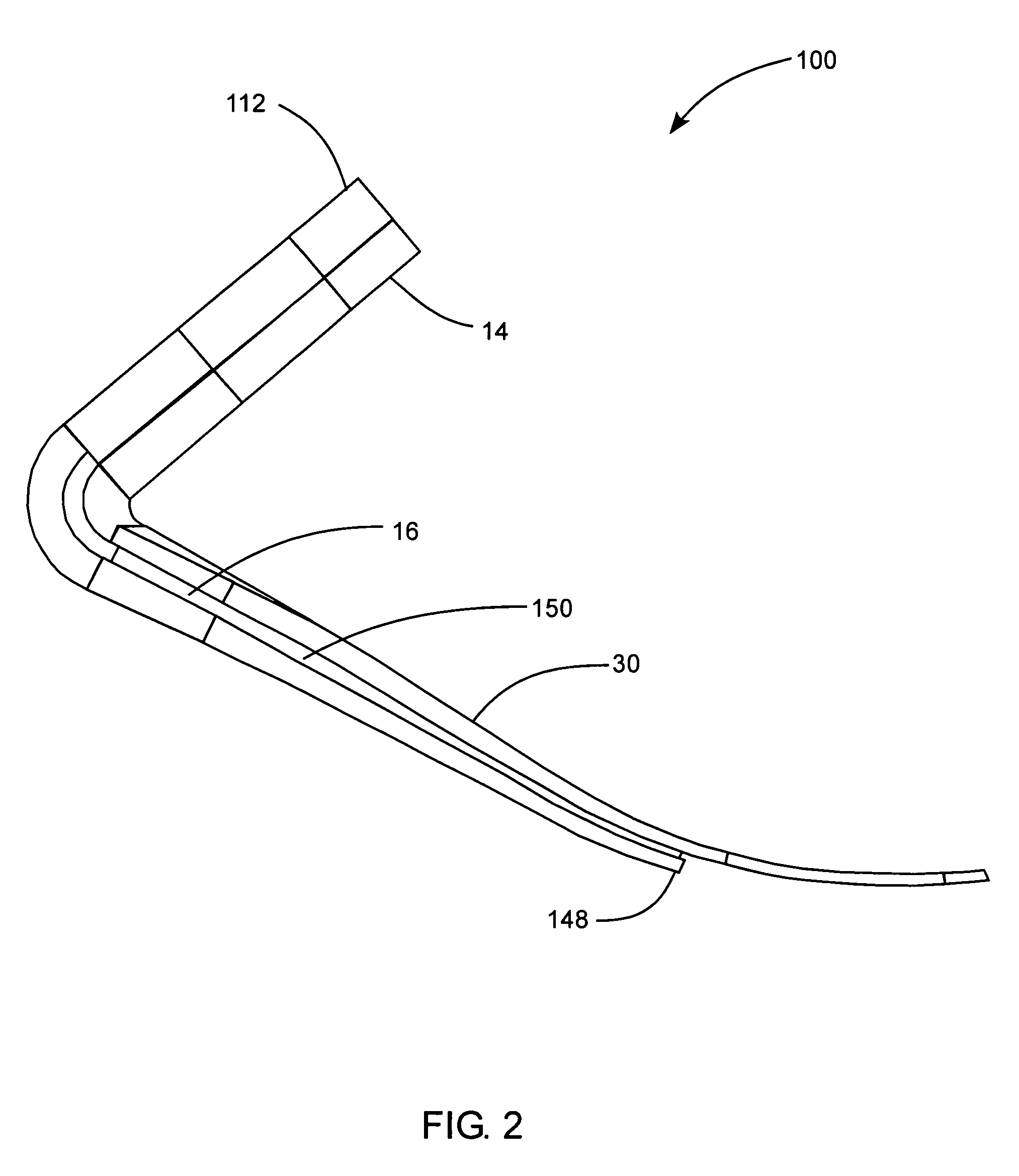
[0021]The present invention provides generally for a prosthetic foot having a longer upper elongated forefoot and a shorter lower elongated forefoot. The upper forefoot extends through an attachment section, downward through an ankle section, and forward through an arch section to a toe section positioned at a toe location of a natural foot. The lower forefoot member extends through an attachment section, downwar...


PUM


Abstract

The invention provides a prosthetic foot device including an elongated upper forefoot portion extending through an upper attachment section, forwardly through an arch section, and to a toe section positioned at a toe location of a natural foot. The foot device also includes an elongated lower forefoot portion extending through an upper attachment section attached to the attachment section of the upper forefoot portion, and forwardly under the arch section of the upper forefoot portion to a terminal end positioned under the ball location of a natural foot and rearward of the toe section of the upper forefoot portion.

Description

PRIORITY CLAIM[0001]Benefit is clamed of U.S. Provisional Patent Application Ser. No. 60 / 873,402, filed Dec. 6, 2006, which is herein incorporated by reference in its entirety for all purposes.BACKGROUND OF THE INVENTION[0002]1. Field of the Invention[0003]The present invention relates generally to foot prosthetic devices.[0004]2. Related Art[0005]Many individuals have lost a limb for various reasons including war, accident, or disease. In most instances these individuals are not only able to live relatively normal lives, but physically active lives as well. Often times, these individuals are aided in their everyday lives by a prosthetic limb. The objective of prosthesis is to provide an artificial limb that simulates the function and natural feel of the replaced limb.[0006]With respect to prosthetic feet, the development of a functional and natural artificial foot has been limited only by material and imagination. Many designs have attempted to copy the anatomy of the foot or simul...

Claims


Application Information

Patent Timeline
Patent Type & Authority Patents(United States)
IPC IPC(8): A61F2/66A61F2/68
CPCA61F2/66A61F2002/5001A61F2002/5007A61F2002/5055A61F2002/6621A61F2002/6642A61F2002/665A61F2002/6664A61F2002/6678A61F2002/6685
Inventor CHRISTENSEN, ROLAND J.BOREN, MARCUS
Owner FREEDOM INNOVATIONS INC
Why Eureka
Try Eureka