Anchoring device

a technology of anchoring device and screw head, which is applied in the direction of flooring, building reinforcements, construction, etc., can solve the problems of reducing the resistance of the head of the fastening screw and/or the nail between the boards, affecting the stability of the board, so as to achieve the effect of easy cracking, easy cracking, and increased resistance to cracking

Inactive Publication Date: 2006-05-25
PELC ROBERT J
View PDF49 Cites 21 Cited by
  • Summary
  • Abstract
  • Description
  • Claims
  • Application Information

AI Technical Summary

Benefits of technology

[0021] The plastic comprising the top element can be rigid plastic but flexible plastic is generally preferred. By flexible is meant that the plastic cannot easily be broken by normal swelling and flexing of the deck boards. Even when the plastic is rigid, though flexing and / or swelling of adjacent boards may crack or even crumble the plastic, the metal reinforcing can retain functional anchoring stability. When the plastic is flexible, there is more resistance to cracking, breaking or crumbling caused by flexing and / or swelling and the rigidity of the anchor is maintained by the metal plate.

Problems solved by technology

Though such anchoring devices are an effective means for convenient precision spacing and attachment of the floor boards to joists and / or each other during initial construction, they are subject to weather related failure and the visibility of the heads of fastening screws and / or nails between the boards is generally found ornamentally undesirable.
Commercially available anchoring biscuits of the aforesaid type are manufactured from rigid molded plastics, which under the stress of flexion and compression due to deck use and changing weather conditions the top biscuit element is known to crack or break thus losing its ability to anchor and / or prevent warping of the boards.
Though vertical members conveniently provide precision spacing between boards during initial construction, the swelling of laid boards during wet weather conditions tends to tightly compress the vertical members and though they may not break or crumble, their resistance to same can exacerbate warping of the boards.
The location of a center hole for affixing a screw or nail leaves an exposed, usually stainless steel nail or screw head, which many consider an undesirable ornamental blemish to the deck.
Further, though nail and screw fastening means are desirable for securely fastening the anchors, plastic anchors generally have little tolerance for over-tightening and fastening has to be skillfully handled to avoid driving the screw or nail head though the plastic top element leaving a loosely fastened and / or failed anchor.

Method used


Image

  • Anchoring device
  • Anchoring device
  • Anchoring device

Examples


Embodiment Construction

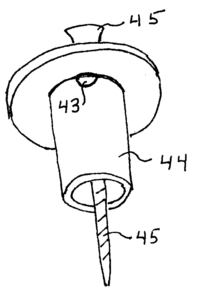
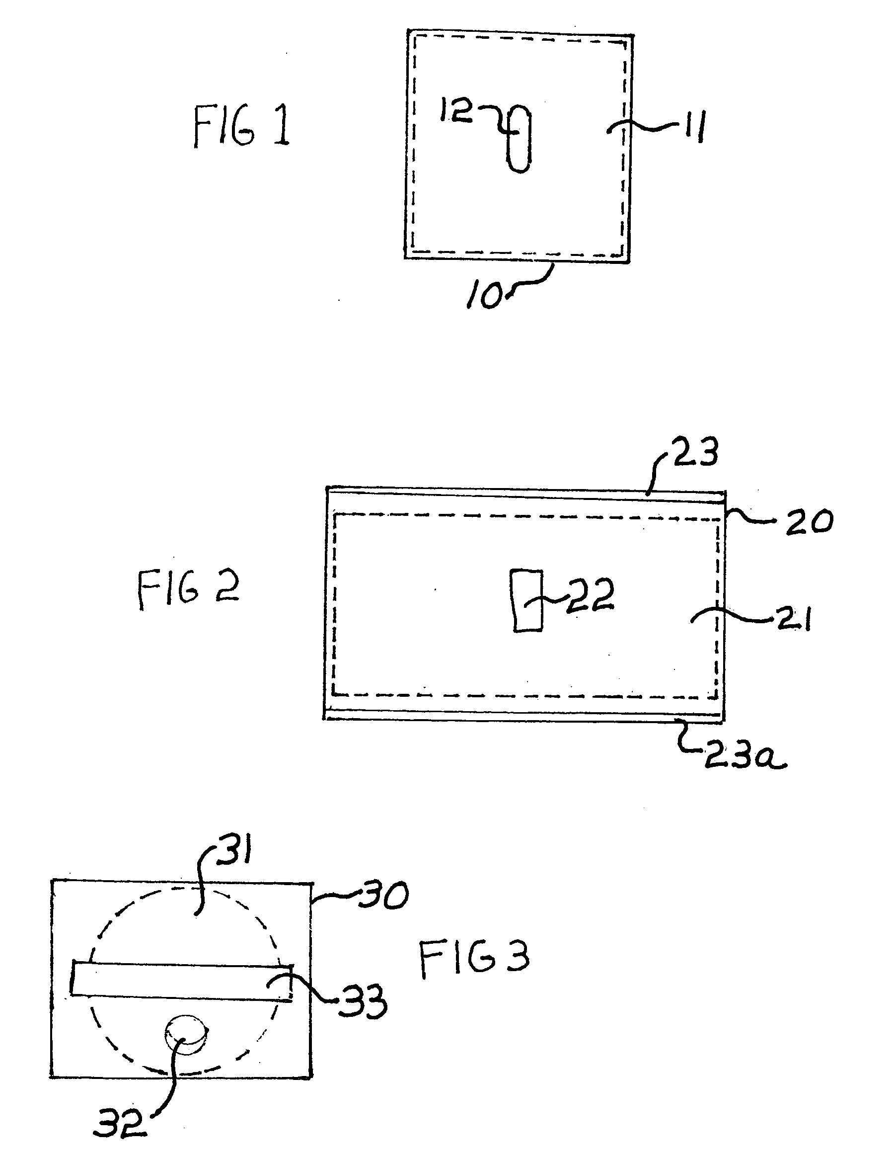
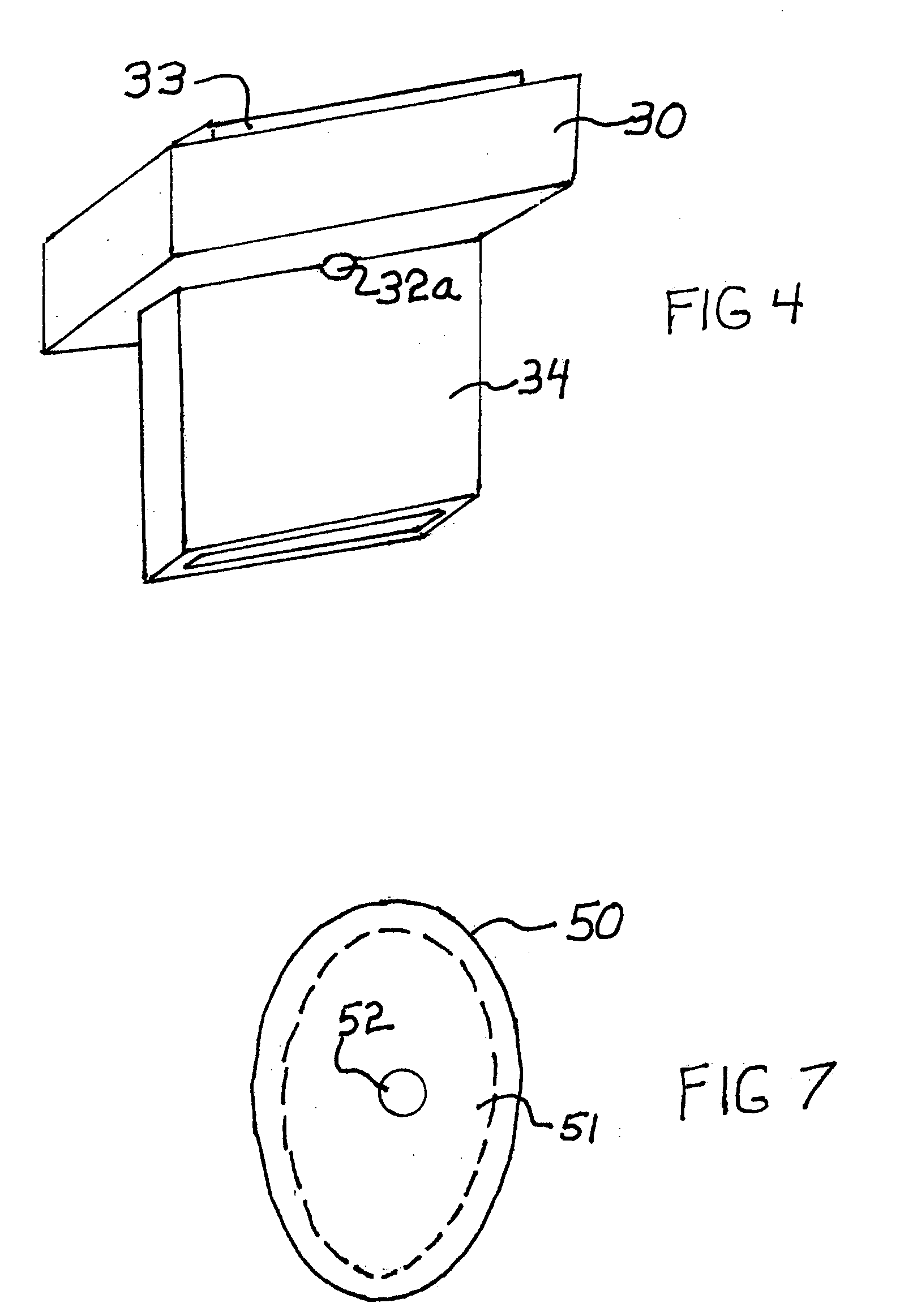
[0039] Referring now to FIG. 1 wherein is illustrated a top plan view of an embodiment of the anchoring device of the invention having a generally square top element 10, with the metallic element 11 being outlined in dotted line, and also being generally square, having an oblong fastening opening 12 therethrough. This arrangement of the invention shows plastic surrounding the sides and exterior peripheral edge of metallic element, with the peripheral edge of the metallic element at a generally central opening not being covered by plastic. This embodiment is generally desirable for use with flat laid boards collapsible hollow rectilinear shoulder 33 extending upwardly from the top side of the top element and collapsible hollow rectilinear vertical element 34 extending downwardly from the underside thereof. This embodiment is particularly preferred for use with flat laid boards which undergo significant climatical dimensional changes. The offset placement of the fastening opening allo...


PUM


Abstract

An anchoring device is disclosed comprising a generally horizontal top element having an elongate, generally vertical, collapsible element extending downwardly from the underside thereof, the horizontal top element comprises a metallic plate reinforced plastic.

Description

[0001] This invention relates to an anchoring device for retaining adjacent boards in precision spaced alignment, being particularly suitable for use with outdoor platform deck construction. BACKGROUND OF THE INVENTION [0002] Outdoor spaced board platforms, generally referred to as decks, have become popular additions to homes, offices, restaurants and the like. They generally comprise a plurality of elongate, flat laid, closely spaced boards, connected to and supported on their bottom surface by framing with spaced joists, stringers, beams and the like forming a secure floor. Though the boards are generally cut from natural wood, they have been increasing manufactured from various compositions of wood and / or other cellulosic materials with various resins, and even plastics and various metals. The top surface of the boards is generally referred to as the face side of a board and the facing elongate sides of adjacent flat laid boards is generally referred to as the edges of a board. ...

Claims


Application Information

Patent Timeline
Patent Type & Authority Applications(United States)
IPC IPC(8): E04B1/38
CPCE04F15/02E04F15/04E04F2015/02094
Inventor PELC, ROBERT J.
Owner PELC ROBERT J
Why Eureka
Try Eureka