Methods and systems for in situ manufacture and installation of non-metallic high pressure pipe and pipe liners

a technology of high-pressure pipes and in situ manufacturing, which is applied in the direction of manufacturing tools, other domestic objects, mechanical equipment, etc., can solve the problems of inability to meet the requirements of the customer, and failure of the wrap or possibly the axial tape first, etc., and achieves 100% coverage

Active Publication Date: 2009-12-17
SMART PIPE COMPANY
View PDF99 Cites 64 Cited by
  • Summary
  • Abstract
  • Description
  • Claims
  • Application Information

AI Technical Summary

Benefits of technology

[0041]The monitoring system package and reinforcement is protected by a polymeric cover or jacket that, in one aspect, is formed from a tape of thermoplastic film with partially cured butyl rubber adhesive orbitally wound on the pipe or pipe liner. The cover is wound such that 100% coverage is obtained. The monitoring system package and reinforcement is, optionally, protected by a polymeric cover or jacket that, in one aspect, is formed from a sheet of material whose width is approximately the same as the circumference of a reinforced pipe liner made, e.g. of polyolefin, nylon, polyvinyl chloride (PVC), high density polyethylene and the like. The sheet, in one aspect, is rolled to form a continuous cylinder that fits tightly around the pipe and is welded to itself to prevent incursion of external debris and or fluids. The cover is on top of the fiber optic packages to protect them from wear and handling damage during folding and pulling into the host pipe. Alternatively a cover is made b

Problems solved by technology

In certain aspects, the process speed is limited by the time to weld—including a time to cool the weld-in line if a finished length of core pipe is produced.
The wrap or possibly the axial tapes will fail first.
TOWS may be used but, in certain aspects, tows do

Method used


Image

  • Methods and systems for in situ manufacture and installation of non-metallic high pressure pipe and pipe liners
  • Methods and systems for in situ manufacture and installation of non-metallic high pressure pipe and pipe liners
  • Methods and systems for in situ manufacture and installation of non-metallic high pressure pipe and pipe liners

Examples


Embodiment Construction

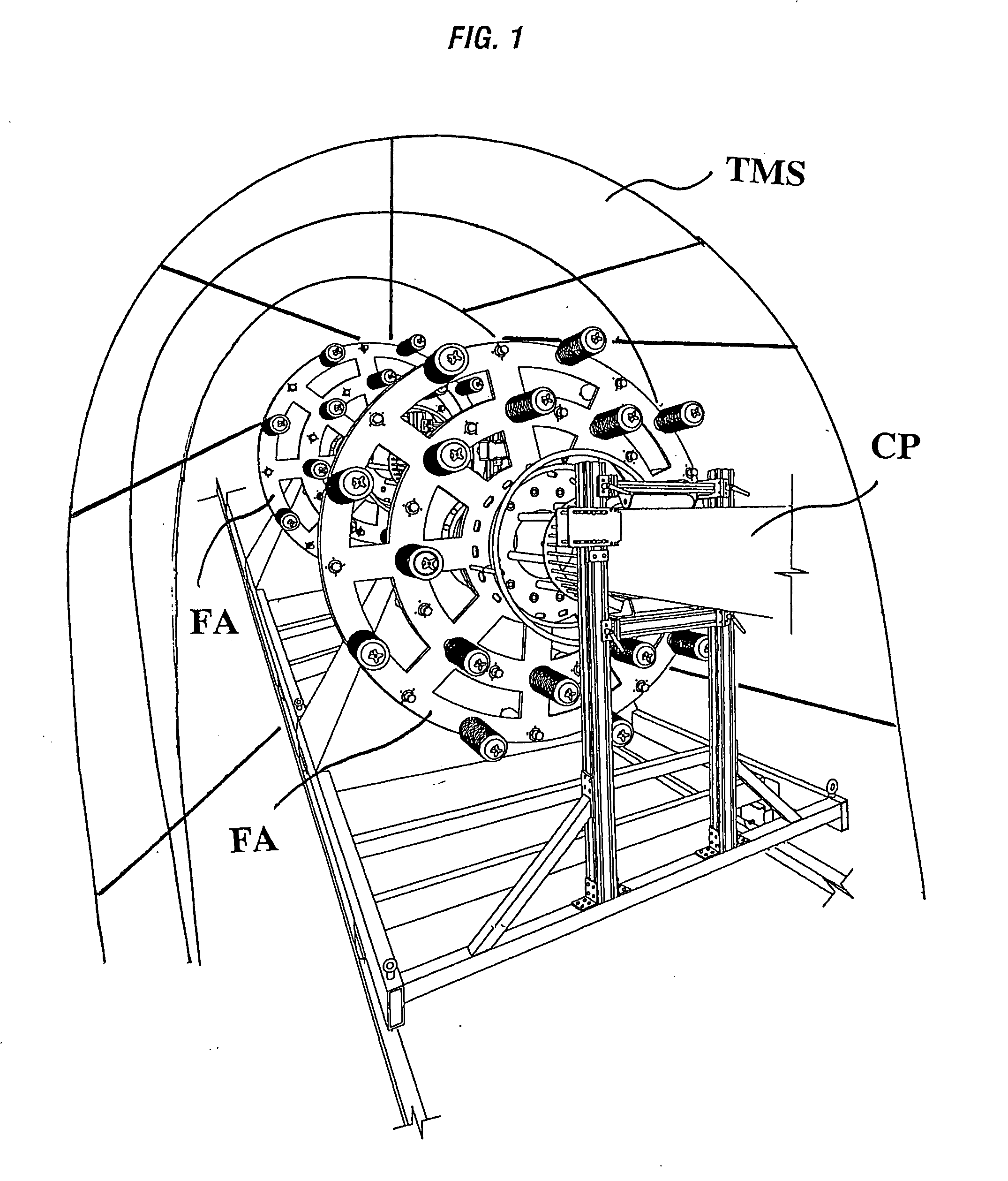
[0082]In one embodiment, the construction and installation of a high-pressure liner according to the present invention are done on site nearly simultaneously; e.g. in a temporary manufacturing shelter TMS (see FIG. 1) which protects equipment used in methods according to the present invention as well as personnel during manufacturing and installation. One end of a host pipe (the pipe to be lined and / or replaced) is exposed, and, if necessary, a long, temporary manufacturing structure, e.g., a tent or portable enclosure (e.g. shelter TMS), is erected to protect material, control systems and workers from the elements. At the terminus of the host pipe is equipment and computer control systems designed primarily to help pull and guide the new pipe through the host pipe.

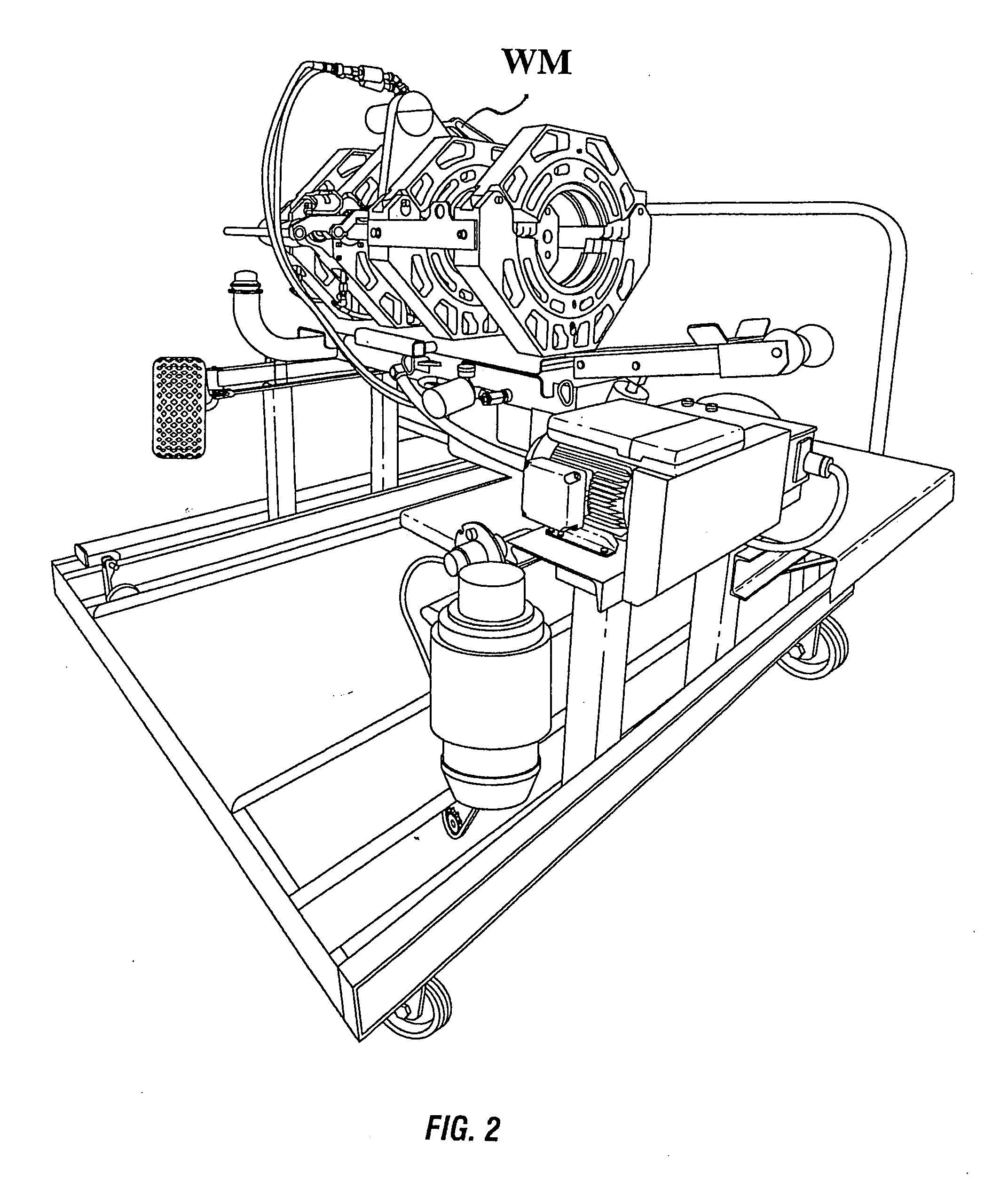
[0083]The manufacturing tent, in certain aspects, up to 500 feet long or more, is the site of an intricate assembly line that connects, wraps, and prepares the new pipe for insertion into the host pipe. According to the p...


PUM

PropertyMeasurementUnit
Lengthaaaaaaaaaa
Lengthaaaaaaaaaa
Lengthaaaaaaaaaa

Abstract

Pipe with a liner or core pipe and a liner or core pipe which is insertable into a host pipe, the liner or core pipe including, in certain aspects, a pipe made of temperature-resistant non-metallic corrosion-resistant material; first and second strengthening wraps around the pipe; a plurality of spaced-apart axial strength members or pulling tapes on the pipe; and a protective outer wrap on the pipe. This abstract is provided to comply with the rules requiring an abstract which will allow a searcher or other reader to quickly ascertain the subject matter of the technical disclosure and is submitted with the understanding that it will not be used to interpret or limit the scope or meaning of the claims, 37 C.F.R. 1.72(b).

Description

[0001]CROSS REFERENCE TO RELATED APPLICATION[0002]This application is a continuation-in-part of U.S. application Ser. Nos. 11 / 033,962 filed 12 Jan. 2005 and 12 / 317,376 filed Dec. 22, 2008. The present invention and application, under the Patent Laws, claim the benefit of priority from U.S. Application Ser. No. 61 / 009,110 filed 26 Dec. 2007, Ser. No. 12 / 317,376 filed Dec. 22, 2008, and Ser. No. 11 / 033,962 filed 12 Jan. 2005; and said Applications are fully incorporated herein for all purposes.BACKGROUND OF THE INVENTION[0003]1. Field of the Invention[0004]The present invention in certain aspects, is directed to: systems and methods for in-situ manufacture and installation of non-metallic high-pressure composite pipe and pipe liners; to lined pipe and pipelines; to high-pressure pipe liners; to pipelines with liners and fiber optic sensors; to methods for lining pipe and pipe liners; in certain particular aspects, to continuous reinforced thermoplastic pipe liner intended for use as a...

Claims


Application Information

Patent Timeline
IPC IPC(8): F16L9/14B23P11/00
CPCB29K2023/0675B29C66/1142B29C53/805B29C53/58B29K2023/083B29K2023/0691B29K2105/0079B29C63/343B29C65/20B29K2023/065B29D23/001F16L11/12Y10T29/49826B29L2023/006F16L55/1656B29C65/8292B29K2023/086B29C66/5221B29C65/00
Inventor STRINGFELLOW, WILLIAM D.BETHEL, KYLEEKLUND, ARONCATHA, STEPHEN C.CHARBONEAU, KENNETH R.
Owner SMART PIPE COMPANY
Why Eureka
Try Eureka