Fiber Coupling Technique on a Waveguide

a waveguide and fiber technology, applied in the field of optical fiber coupling assemblies, can solve problems such as signal loss, and achieve the effects of reducing polishing difficulties, less fragile, and convenient manufacturing

Active Publication Date: 2013-01-24
CIENA
View PDF7 Cites 66 Cited by
  • Summary
  • Abstract
  • Description
  • Claims
  • Application Information

AI Technical Summary

Benefits of technology

[0018]One of ordinary skill in the art will understand that in the optical coupling assembly according to this aspect of the invention, the light-guiding fiber core of the optical fiber is generally parallel to the light-guiding path of the planar waveguide, so that the orientation of the reflection interface with respect to the waveguide coupling element is determined by a cut angle of the angled tip. In a preferred embodiment, this cut angle is greater than about 45 degrees, which advantageously allows the angled tip to be more easily manufactured than in prior art designs. Indeed, a steeper cut angle reduces polishing difficulties since the resulting angled tip is less fragile and prone to chipping. As will be understood by one skilled in the art, chipping of the angled tip of the optical fiber may cause signal loss since the output signal generally exits in the vicinity of the fiber end.
[0019]One of ordinary skill in the art of waveguide design will also recognize the advantage of having the flexibility of reversing the waveguide propagation direction with respect to the fiber propagation direction. In particular, this flexibility generally eases the constraints imposed on the design of the optical coupling assembly. As a result, lightwave circuits including one or more optical coupling assemblies as above may support denser waveguide integration schemes. Furthermore, path crossovers on waveguides of such circuits, which may lead to the degradation of optical signals, may be reduced.

Problems solved by technology

As will be understood by one skilled in the art, chipping of the angled tip of the optical fiber may cause signal loss since the output signal generally exits in the vicinity of the fiber end.

Method used


Image

  • Fiber Coupling Technique on a Waveguide
  • Fiber Coupling Technique on a Waveguide
  • Fiber Coupling Technique on a Waveguide

Examples


Embodiment Construction

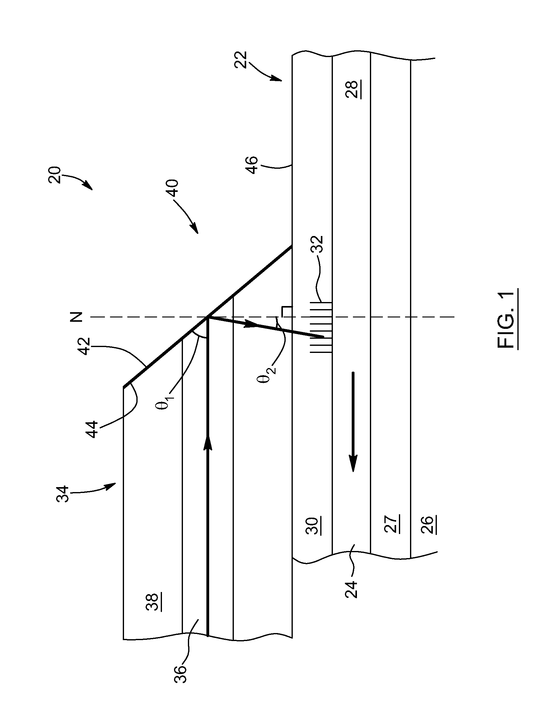
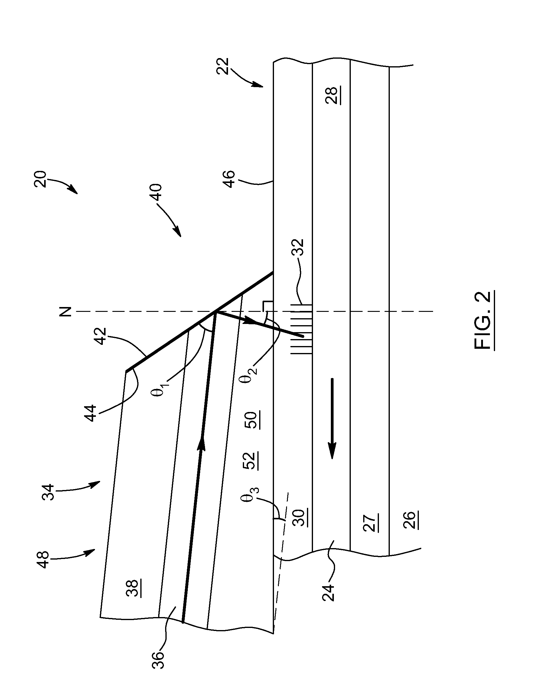
[0036]The present invention generally relates to optical coupling assemblies for coupling light from an optical fiber into a planar waveguide.

[0037]Embodiments of the present invention may be particularly useful in any applications where it is necessary to couple light propagating in an optical fiber into a planar waveguide, or vice versa. In particular, although embodiments described herein may refer to the coupling of light from an optical fiber into a planar waveguide, it will be understood that the optical coupling assembly may also be employed in order to couple light from a planar waveguide into an optical fiber. Optical coupling assemblies according to embodiments of the present invention may be part of photonic integrated circuits used for various applications including, without being limited to, telecommunications, instrumentation, signal processing, and optical sensors.

[0038]FIG. 1 shows a schematic cross-sectional side view of an exemplary optical coupling assembly 20 acc...


PUM


Abstract

An optical coupling assembly for coupling light from an optical fiber including an angled tip into a planar waveguide via a waveguide coupling element is provided. In one embodiment, the optical fiber extends along the planar waveguide with the angled tip positioned such that light propagating in the optical fiber is coupled by the waveguide coupling element to propagate in the planar waveguide in counter propagation with respect to a fiber propagation direction. In another embodiment, the optical fiber includes a tapered peripheral portion tapering toward the angled tip and is disposed over the planar waveguide with the tapered peripheral portion extending therealong such that light propagating in the optical fiber is coupled to propagate in the planar waveguide with either forward or counter propagation. Embodiments of the present invention may be part of various photonic integrated circuits and may be manufactured more easily than known optical coupling assemblies.

Description

CROSS-REFERENCE TO RELATED APPLICATIONS[0001]This application is a Nonprovisional of U.S. Patent Application Ser. No. 61 / 509,256, filed on Jul. 19, 2011, the disclosure of which is incorporated herein by reference in its entirety.FIELD OF THE INVENTION[0002]The present invention relates to the field of coupling optical fibers to planar waveguides, and more particularly concerns optical coupling assemblies for the coupling of light between an optical fiber and a planar waveguide.BACKGROUND OF THE INVENTION[0003]As telecommunication systems evolve from 10 Gb / s transmission rate to 40 Gb / s and now 100 Gb / s, more sophisticated modulation scheme are developed. For example, phase modulation is increasingly used rather than simpler amplitude modulation. At 100 Gb / s, coherent communication involving polarization multiplexing further adds to the required complexity at the transmitter and receiver sides. In particular, more optical processing is required and calls for photonic integrated solu...

Claims


Application Information

Patent Timeline
Patent Type & Authority Applications(United States)
IPC IPC(8): G02B6/30G02B6/26G02B6/34
CPCG02B6/30G02B6/262G02B6/124G02B6/34
Inventor PELLETIER, FRANCOISROBIDOUX, GUILLAUMEPAINCHAUD, YVES
Owner CIENA
Why Eureka
Try Eureka