Connector assembly having an interlocking system

a technology of interlocking system and connector assembly, which is applied in the direction of coupling device connection, coupling parts engagement/disengagement, incorrect coupling prevention, etc., can solve the problems of structural instability, structural instability, and insufficient mechanical strength of interlocking portions of male and female connectors in the described prior art structur

Inactive Publication Date: 2002-06-13
JST MFG CO LTD
View PDF0 Cites 20 Cited by
  • Summary
  • Abstract
  • Description
  • Claims
  • Application Information

AI Technical Summary

Problems solved by technology

The interlocking portions of the male and female connectors in the described prior art structure are not necessarily sufficient in their mutual retention and in their own mechanical strength.
This is because the hinge-shaped legs connecting the lock arm to the female housing are comparatively weak.
The prior art structure has rendered unstable its interlocking state, often failing to ensure reliable electrical connections, when used in certain vibrating machines such as automobiles.
`Snap-fit` feeling has also been insufficient when engaging the lockable lug with the lock arm, making it difficult to confirm their mutual connection from outside.
Additionally, the handling and pulling of wire ends around the female connector has sometimes imparted such a distortion to the female housing as causing disengagement of the lock arm from the lockable lug.
However, this would result in another problem that they could not easily engage with and not smoothly disengage from each other.
Due to such a gap, electric wire ends belonging to an adjacent harnesses have often pressed undesirably the push lever to unlock the lockable lug out of the lock arm.
This drawback has been most prominent in case of arranging a number of wire ends within a narrow space such as those available in automobiles.
In addition, electric wire ends of the neighboring harnesses have sometimes got in the gap to be jammed therein, accidentally catching the push lever and hindering the wiring operations.

Method used


Image

  • Connector assembly having an interlocking system
  • Connector assembly having an interlocking system
  • Connector assembly having an interlocking system

Examples


Embodiment Construction

[0020] Now some embodiments of the present invention will be described with reference to the drawings.

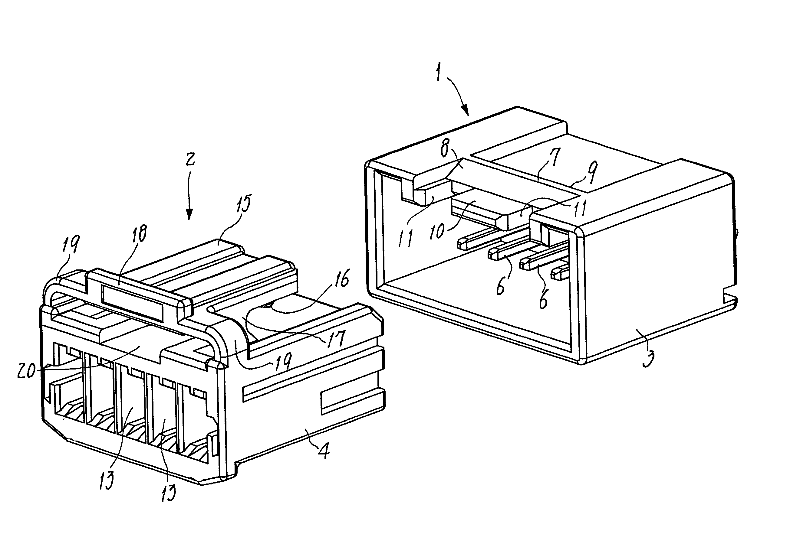
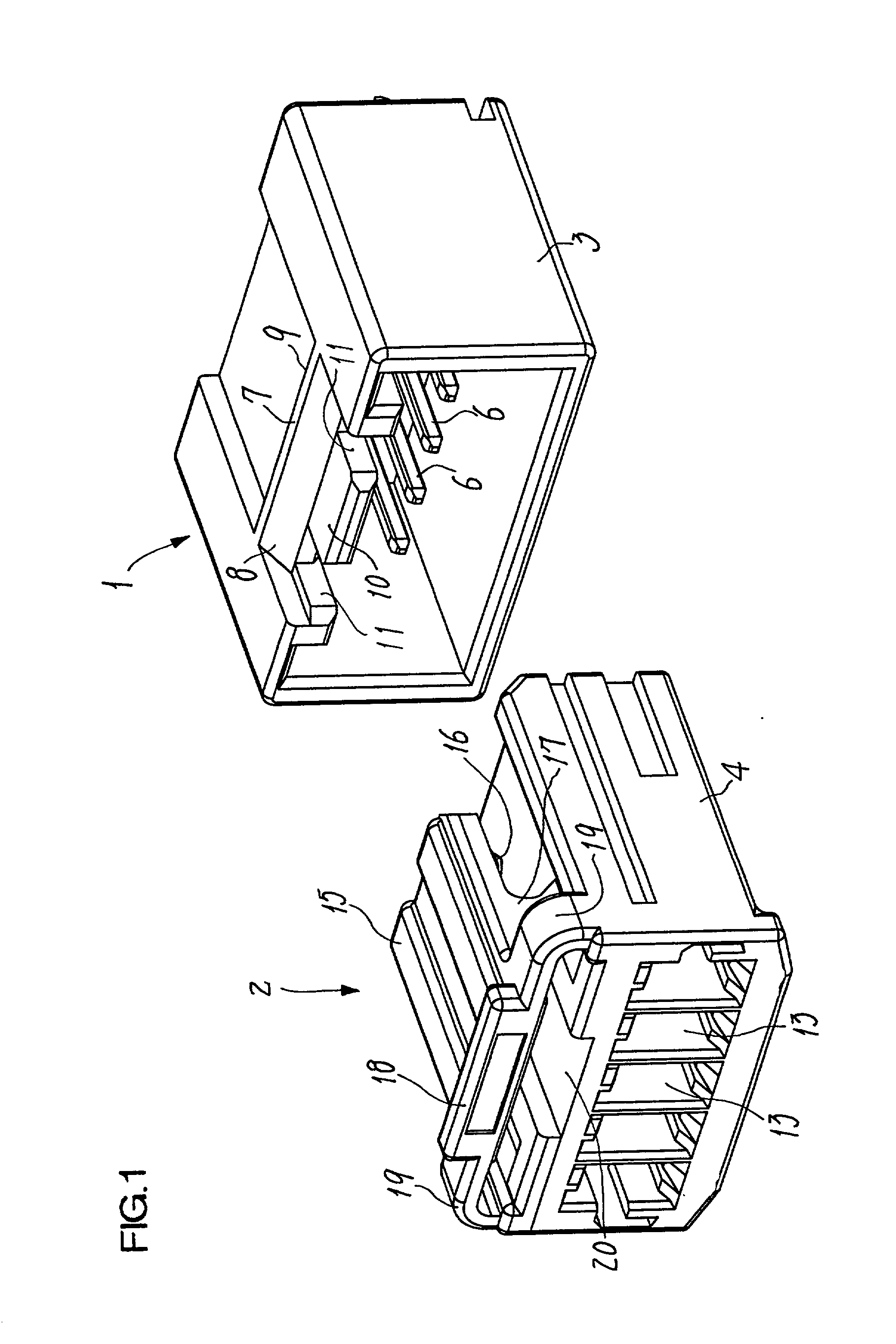
[0021] FIG. 1 shows a connector assembly of the invention having an interlocking system. This assembly is composed of a pair of connectors that are a male connector 1 and a female connector 2 to be fitted thereon. The male connector 1 comprises its own housing (viz., male housing) 3, with the female connector 2 likewise comprising its own housing (viz., female housing) 4. Both the housings 3 and 4 are made of an insulating resin such as Nylon (a registered trademark). Socket contacts 22 fixed in the female housing 4 are separated from each other to form the female connector 2, although only this housing 4 is shown in FIG. 1. As seen in FIG. 6, electric wire ends 21 are secured in the respective socket contacts 22.

[0022] The male housing 3 is shaped generally as a parallelepiped box having a fore end opening, and insert-molded such that a plurality of pin contacts 6 penetrate its bot...


PUM


Abstract

A connector assembly has a male housing (3), a female housing (4) and an interlocking system composed of a lockable lug (7) on the male housing. A lock arm (15) on the female housing has a pawl (16) engaging with the lug, a pair of elastically deforming hinge-shaped legs (17) integrally support the lock arm, and a push lever (18) is disposed at the rear end of lock arm extending rearwards beyond the legs. A guide tongue (10) intervening between a pair of side slots (11) and protruding forwards from the lug (7) is inserted in between the legs (17) spaced sideways, the slots (11) fitting on the legs at the same time. A pair of bridges (19) continue from the female housing (4) to lateral ends of the push lever.

Description

[0001] The present invention relates to a connector assembly that has an interlocking system for latching a male connector fitted on and engaging with a female connector.PRIOR ART[0002] Many types of connector assemblies each having an interlocking system of this kind are known in the art. The present invention is directed in particular to such an assembly as comprising a male connector housing (hereinafter simply called `male housing`) and a female connector housing (hereinafter simply called `female housing`). The male housing has a lockable lug formed on the outer surface thereof, with the female housing has a lock arm that is formed integral with a pawl capable of engaging with the lockable lug. Elastically deforming hinge-shaped legs secure the lock arm to the outer surface of the female housing, which has also a push lever formed on the rear end of its lock arm and disposed in rear of the hinge-shaped legs.[0003] The interlocking portions of the male and female connectors in t...

Claims


Application Information

Patent Timeline
Patent Type & Authority Applications(United States)
IPC IPC(8): H01R13/639H01R13/62H01R13/627
CPCH01R13/6272H01R13/62
Inventor CHEN, PING
Owner JST MFG CO LTD
Why Eureka
Try Eureka