Charger, image forming apparatus, and charge control method

a charge control and image forming technology, applied in the direction of electrographic process apparatus, instruments, corona discharge, etc., can solve problems such as irregular charge, and achieve the effect of effective realizing high-quality image formation, preventing banding and resisting shi

Inactive Publication Date: 2010-11-16
SEIKO EPSON CORP
View PDF5 Cites 4 Cited by
  • Summary
  • Abstract
  • Description
  • Claims
  • Application Information

AI Technical Summary

Benefits of technology

[0009]An object of the present invention is to provide a charger capable of preventing, in charging of an image carrier using a primary and secondary charging members, banding occurring at the time when a secondary charging member is cleaned, an image forming apparatus incorporating the charger, and a charge control method.
[0010]In order to achieve the above object, according to the present invention, at the cleaning time when an image is not formed, the controller applies, to the first charging member, a voltage whose absolute value is lower than the absolute value of the discharge start voltage of the first charging member and applies, to the second charging member, a voltage whose absolute value is higher than the absolute value of the discharge start voltage of the second charging member and whose absolute value is higher than voltage applied to the first charging member. That is, the magnitude relation in the absolute values of the application voltages to the primary and secondary charging members is reversed between at the image formation time and at the cleaning time. As a result, foreign matters such as residual toner adhered to the secondary charging member can be removed therefrom and moved to the image carrier. This allows achievement of satisfactory charge of the image carrier over a long period of time, thereby effectively realizing high quality image formation.
[0011]In addition, at the time of cleaning the secondary charging member, the surface potential of the image carrier brought into contact with the secondary charging member can be maintained at a constant value. This prevents formation of a charged part and non-charged part on the image carrier, making the electrostatic adsorption force between the image carrier and a transfer belt uniform. As a result, a difference is not caused in moving speed of the transfer belt, thereby preventing banding and resist shift.

Problems solved by technology

However, in the contact type charge, there may be a case where residual toner particles passing through a cleaner of the photoconductor or other foreign matters are adhered to the charging member to contaminate it, causing irregular charge.
As a result, a difference is caused in the moving speed of the transfer belt, causing banding.

Method used


Image

  • Charger, image forming apparatus, and charge control method
  • Charger, image forming apparatus, and charge control method
  • Charger, image forming apparatus, and charge control method

Examples


example 1

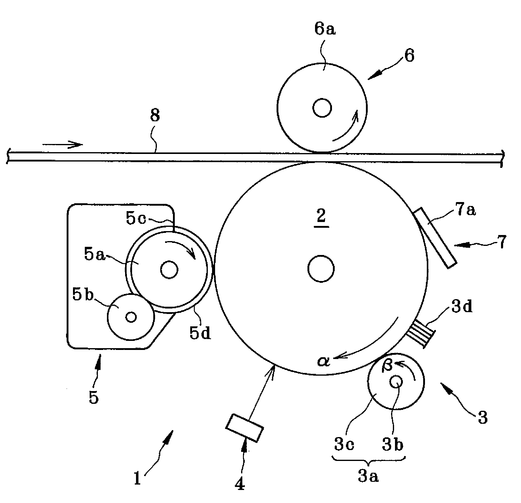
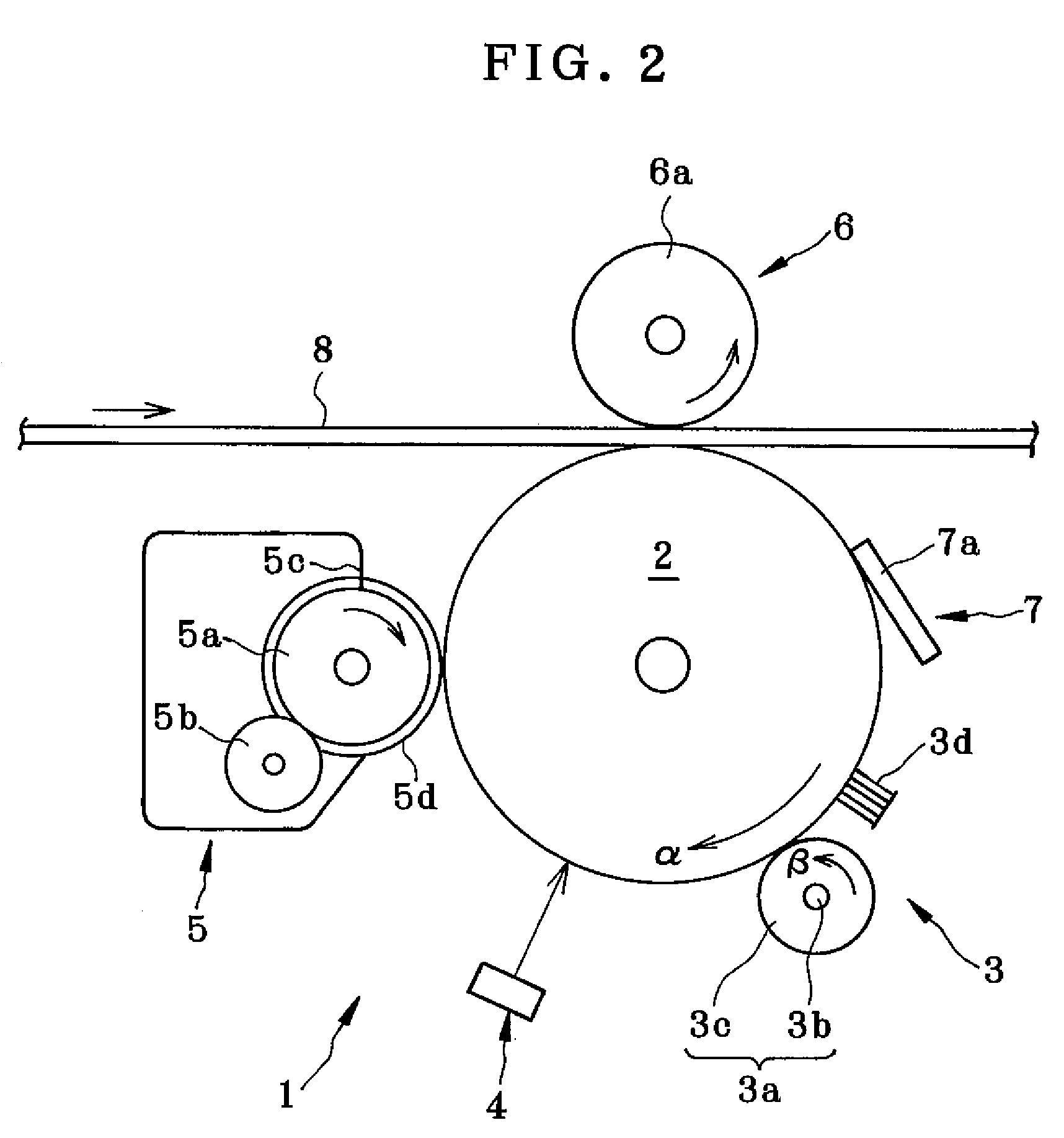
[0078]As shown in Table 2, a DC voltage of −1400 V whose absolute value is higher than the absolute value of the discharge start voltage Vth (V) was applied to the charging roller 3a at the time of bias cleaning and a DC voltage of 0 V whose absolute value is lower than the absolute value of the discharge start voltage Vth (V) was applied to the charging brush 3d. The surface potential of the image carrier at this time was −812 V.

example 2

[0079]As shown in Table 2, a DC voltage of −1200 V whose absolute value is higher than the absolute value of the discharge start voltage Vth (V) was applied to the charging roller 3a at the time of bias cleaning and a DC voltage of 0 V whose absolute value is lower than the absolute value of the discharge start voltage Vth (V) was applied to the charging brush 3d. The surface potential of the image carrier at this time was −620 V.

example 3

[0080]As shown in Table 2, a DC voltage of −1000 V whose absolute value is higher than the absolute value of the discharge start voltage Vth (V) was applied to the charging roller 3a at the time of bias cleaning and a DC voltage of 0 V whose absolute value is lower than the absolute value of the discharge start voltage Vth (V) was applied to the charging brush 3d. The surface potential of the image carrier at this time was −401 V.


PUM


Abstract

A charger includes: a first charging member that contacts an image carrier and a second charging member that contacts the image carrier downstream from the first charging member. At the time of image formation, a voltage higher than the discharge start voltage of the first charging member is applied to the first charging member and a voltage lower than the discharge start voltage of the second charging member and lower than the voltage applied to the first charging member is applied to the second charging member, and at the time when an image is not formed, a voltage lower than the discharge start voltage of the first charging member is applied to the first charging member and a voltage higher than the discharge start voltage of the second charging member and higher than the voltage applied to the first charging member is applied to the second charging member.

Description

CROSS-REFERENCE TO RELATED APPLICATIONS[0001]This application is based upon and claims the benefit of priority from prior Japanese Patent Application No. 2006-334497, filed Dec. 12, 2006, the entire content of which is incorporated herein by reference.BACKGROUND OF THE INVENTION[0002]1. Field of the Invention[0003]The present invention relates to a charger for charging an image carrier, an image forming apparatus of electrophotographic type incorporating the charger, and a charge control method for controlling charging of the image carrier.[0004]2. Description of the Related Art[0005]In a conventional image forming apparatus including an electrophotographic machine, such as an electrostatic copier, a printer, and facsimile, an image is formed as follows. First, after the surface of a photoconductor is uniformly charged by a contact charger, an electrostatic latent image is formed on the surface of the photoconductor by an exposure unit. Then, the electrostatic latent image is develo...

Claims


Application Information

Patent Timeline
Patent Type & Authority Patents(United States)
IPC IPC(8): G03G15/02
CPCG03G15/0216G03G15/0266
Inventor KOBASHI, MASARUMIGITA, KOJINAKATSU, MASASHIKAMOSHIDA, SHINICHI
Owner SEIKO EPSON CORP
Why Eureka
Try Eureka