Image transferring and forming apparatus

a technology of forming apparatus and transferring image, which is applied in the direction of electrographic process apparatus, instruments, optics, etc., can solve the problems of increasing the size of the apparatus, increasing the cost, and deteriorating the image quality, so as to prevent banding

Inactive Publication Date: 2009-02-24
FUJIFILM CORP
View PDF8 Cites 2 Cited by
  • Summary
  • Abstract
  • Description
  • Claims
  • Application Information

AI Technical Summary

Benefits of technology

[0011]The present invention has been made to solve the problems with the conventional technique, and therefore has an object to provide an image forming apparatus capable of preventing image quality deterioration due to banding from occurring and suitably responding to the intended purposes of producing an image with high quality equal to that of a photograph, and also capable of preventing an increase in size of the apparatus so as to make the apparatus compact, in an image forming method such as that in the photographic system in which an image is transferred onto an image receiving medium, and then the transferred image is fixed.
[0040]According to the first and second aspects of the present invention with the above structures, it is possible to provide the image forming apparatus in which an image is first formed on an image formation medium or an intermediate transfer member to be transferred onto the image receiving medium (i.e., recording sheet) and then the transferred image is fixed onto the image receiving medium with the application of pressure (or further by heating) as in an image recording method of the electrophotographic system, capable of preventing banding (i.e., image unevenness) due to a load change of the image receiving medium during transfer from occurring, and also capable of being made compact according to the corresponding receiver media.

Problems solved by technology

In the image forming method in which an image is transferred as described above, load change occurred in the image receiving medium during the transfer of the image leads to an image unevenness (so-called banding), which deteriorates the quality of the image.
However, since a thick image receiving medium is preferred for the print with the high image quality, the forward end entry load is large with the result that banding is liable to occur.
However, as disclosed in Patent Document 2, in order to make the distance (i.e., conveying length) between the transfer position and the fixing position larger than the maximum length of the medium, it is necessary to keep the distance large enough, which leads to an increase in size of the apparatus or an increase in cost.
This further causes the size or the cost of the apparatus to increase.

Method used


Image

  • Image transferring and forming apparatus
  • Image transferring and forming apparatus
  • Image transferring and forming apparatus

Examples


Embodiment Construction

[0052]Hereinafter, a description will be given in more detail of image forming apparatus according to preferred embodiments of the present invention with reference to the accompanying drawings.

[0053]First, an image forming apparatus according to the first aspect of the present invention will be described with reference to FIGS. 1 to 5B.

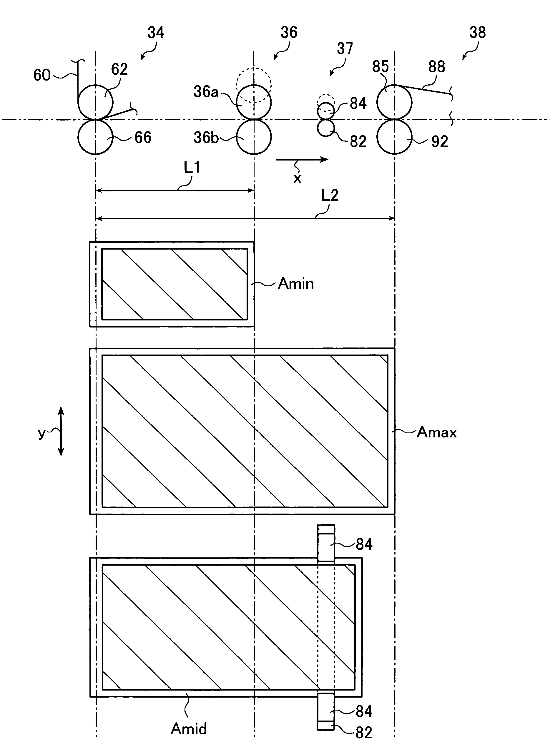
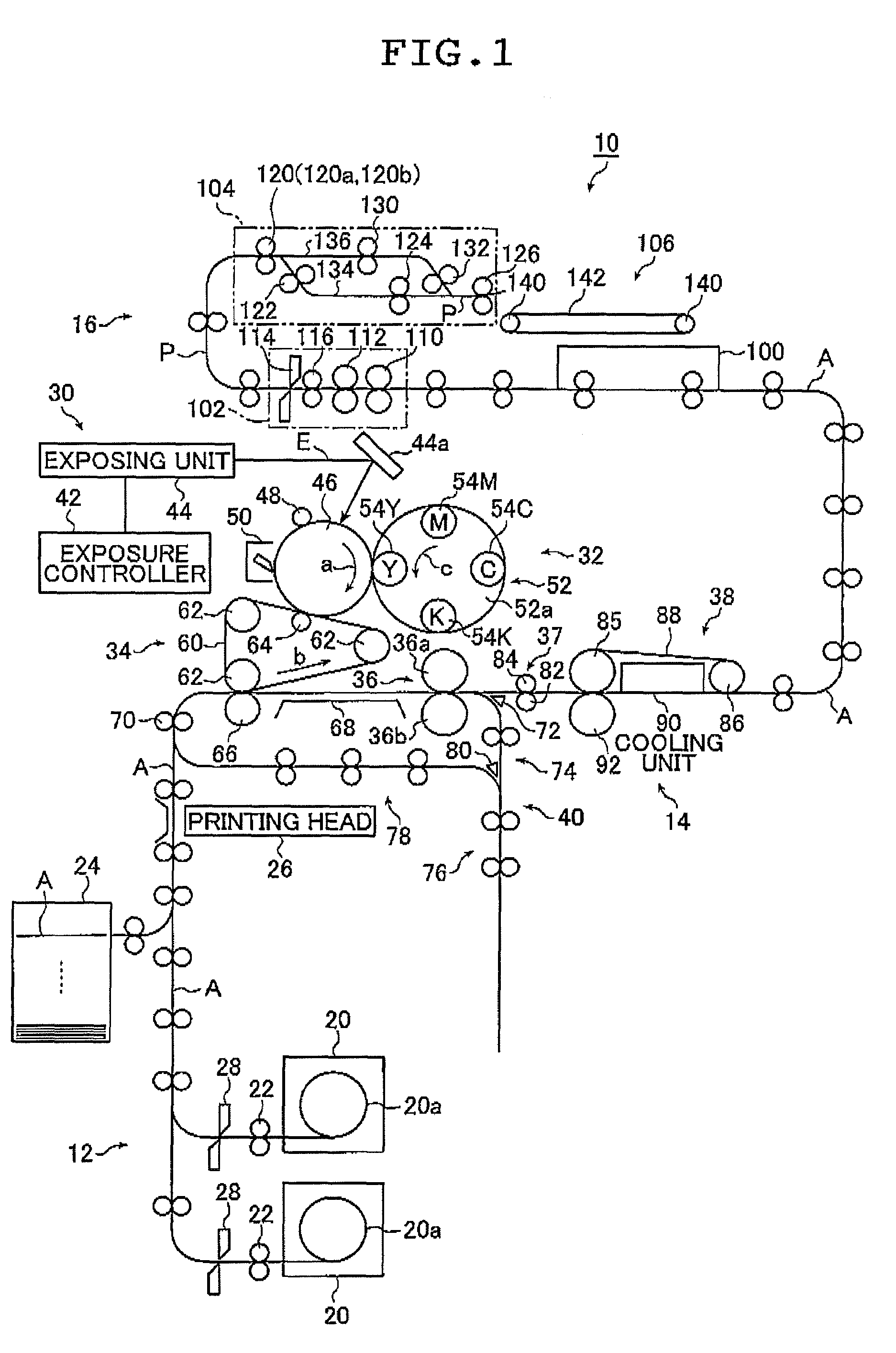
[0054]FIG. 1 is a conceptual diagram showing an embodiment of a printer using an image forming apparatus of the first aspect of the present invention.

[0055]A printer 10 shown in FIG. 1 produces a print by recording an image on a recording sheet A or image receiving medium by an electrophotographic system and basically includes a recording sheet supplying section 12, an image forming section 14, and a cutting / arranging section 16. Various members arranged in commonly known printers as exemplified by means for conveying the recording sheet A (such as a conveying roller pair and a guide member) and a sensor for detecting the recording sheet A are also di...


PUM


Abstract

An image forming apparatus includes a transferring section for transferring an image to an image receiving medium, a primary fixing section for fixing the image by pressurizing the medium and a secondary fixing section for fixing the image. Conveying lengths of the medium from a transfer position to image fixing positions in the secondary fixing section and the primary fixing section are shorter than a maximum length and a minimum length of the medium in the conveying direction, respectively. In case of the medium of the maximum length, the primary fixing section is brought into a non-fixing state and the transfer is completed when the forward end of the medium reaches the secondary fixing section. In case of the medium of the minimum length, the primary fixing section is brought into a fixing state and the transfer is completed when the forward end of the medium reaches the primary fixing section.

Description

BACKGROUND OF THE INVENTION[0001]The present invention relates to an image forming apparatus employing a transfer process for transferring an image to an image receiving medium and a fixing process after the transfer, and more particularly, to an image forming apparatus which is capable of preventing an image unevenness from being caused during image transfer, and of being made compact.[0002]There has been known an image forming method, such as an image recording method of an electrophotographic system, in which an image is first formed on an image formation medium or the image is further transferred from the image formation medium onto an intermediate transfer body from the image formation medium, and then the image is transferred from the image formation medium or the intermediate transfer body onto the image receiving medium (i.e., recording sheet) to be fixed onto the image receiving medium by the application of pressure.[0003]In the image forming method in which an image is tra...

Claims


Application Information

Patent Timeline
Patent Type & Authority Patents(United States)
IPC IPC(8): G03G15/20G03G15/00
CPCG03G15/2064G03G15/657G03G2215/00413G03G2215/00426G03G2215/00805G03G2215/2074G03G2215/2083
Inventor TANABE, TSUYOSHI
Owner FUJIFILM CORP
Why Eureka
Try Eureka