Disc cleaning machinery, disc cleaning device thereof and rotary brush thereof

a disc cleaning machine and disc cleaning technology, applied in carpet cleaners, instruments, photosensitive materials, etc., can solve the problems of insufficient cleaning of the internal portions of the disc, inability to adequately clean the disc, and inability to manufacture a large quantity of low-cost hard disk drives. achieve the effect of improving the cleaning efficiency

Inactive Publication Date: 2010-11-30
HITACHI HIGH-TECH CORP
View PDF17 Cites 5 Cited by
  • Summary
  • Abstract
  • Description
  • Claims
  • Application Information

AI Technical Summary

Benefits of technology

[0012]An object of the present invention is to provide a disc cleaning machine capable of scrubbing discs in the batch and improving the throughput of cleaning processing, while reducing the size of the machine.

Problems solved by technology

Therefore, manufacturers of hard disc devices require the fabrication of a large quantity of low cost hard disc drives.
However, although the disc cleaning device mentioned above can perform batch processing, the scrubbing portion thereof is only of the sheet-fed type in which the discs are cleaned individually.
Therefore, in view of the request of simultaneous cleaning of 2.5 inch discs or smaller, the prior art sheet-fed type disc cleaning device is not appropriate.
In addition to this, since the rotary shaft is inserted into centers of the discs, it is impossible to sufficiently clean internal portions of the discs.
Therefore, the machine is not suitable to clean compact discs.

Method used


Image

  • Disc cleaning machinery, disc cleaning device thereof and rotary brush thereof
  • Disc cleaning machinery, disc cleaning device thereof and rotary brush thereof
  • Disc cleaning machinery, disc cleaning device thereof and rotary brush thereof

Examples


embodiment 1

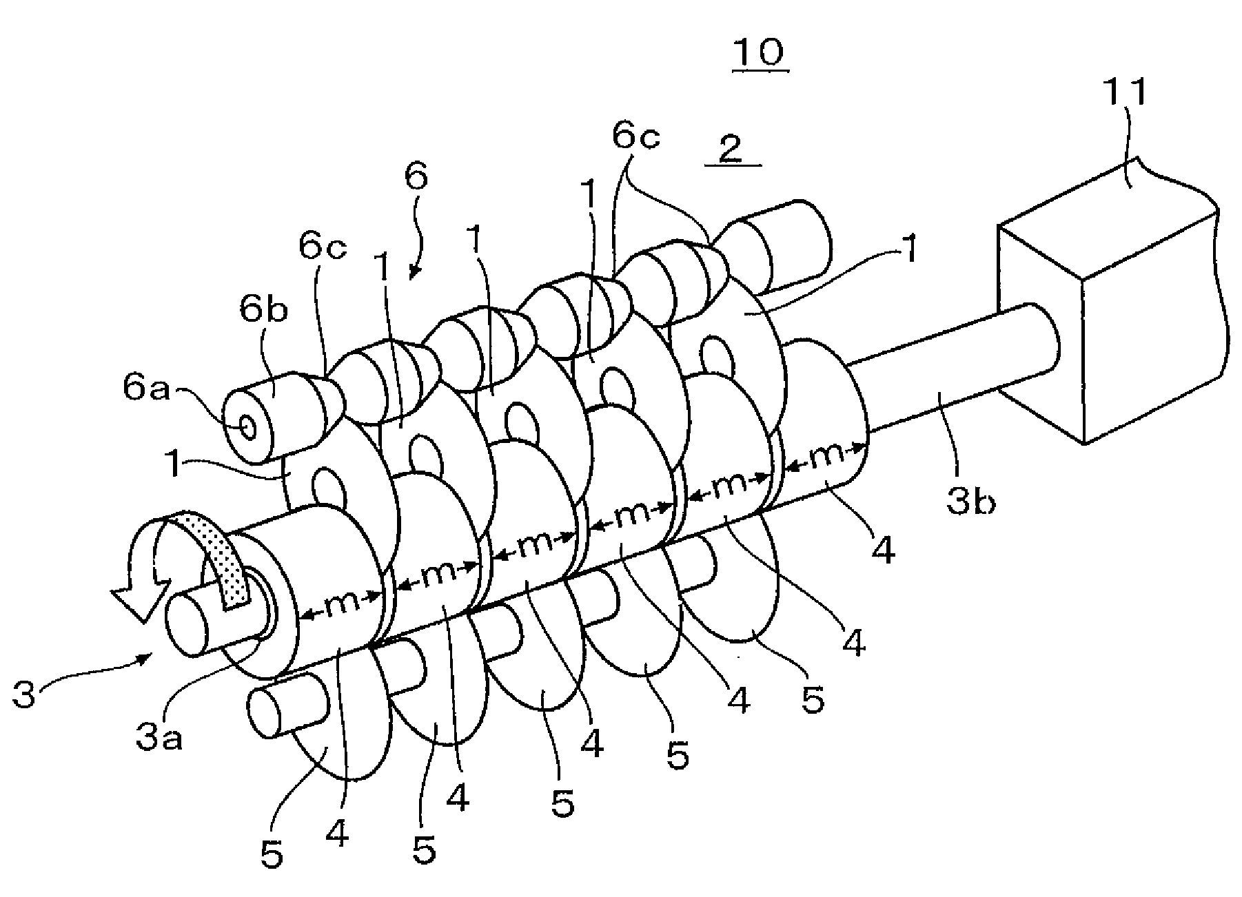
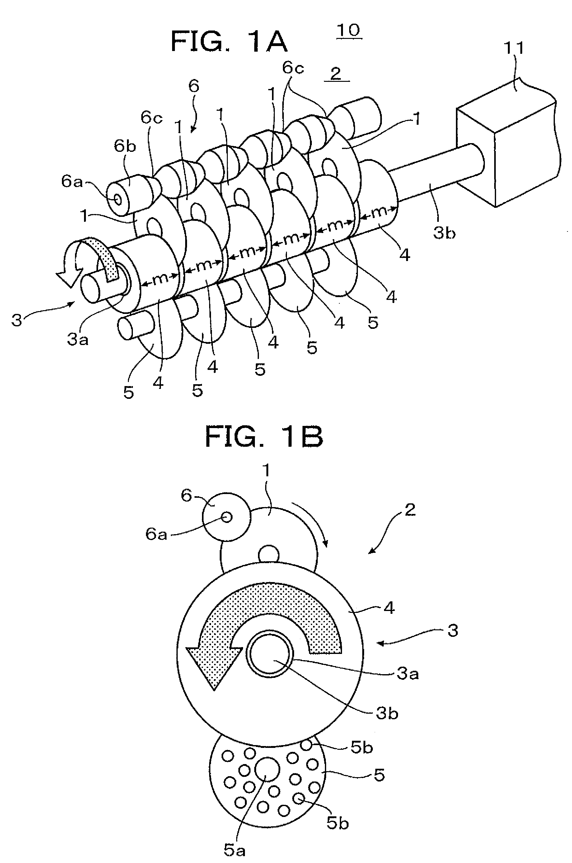
[0050]In FIGS. 1A and 1B, a reference numeral 10 depicts a disc cleaning device (an internal portion of a scrubbing chamber thereof) including discs to be cleaned, a cleaning device 2, a rotary brush unit 3, disc-shaped brushes 4 each constructed by a porous sponge member formed of PVA (polyvinyl alcohol), thickness of which is m. The brushes 4 are mounted on a roller 3a. The rotary blush unit 3 is constructed with the brushes 4, a rotary shaft 3b and the roller 3a.

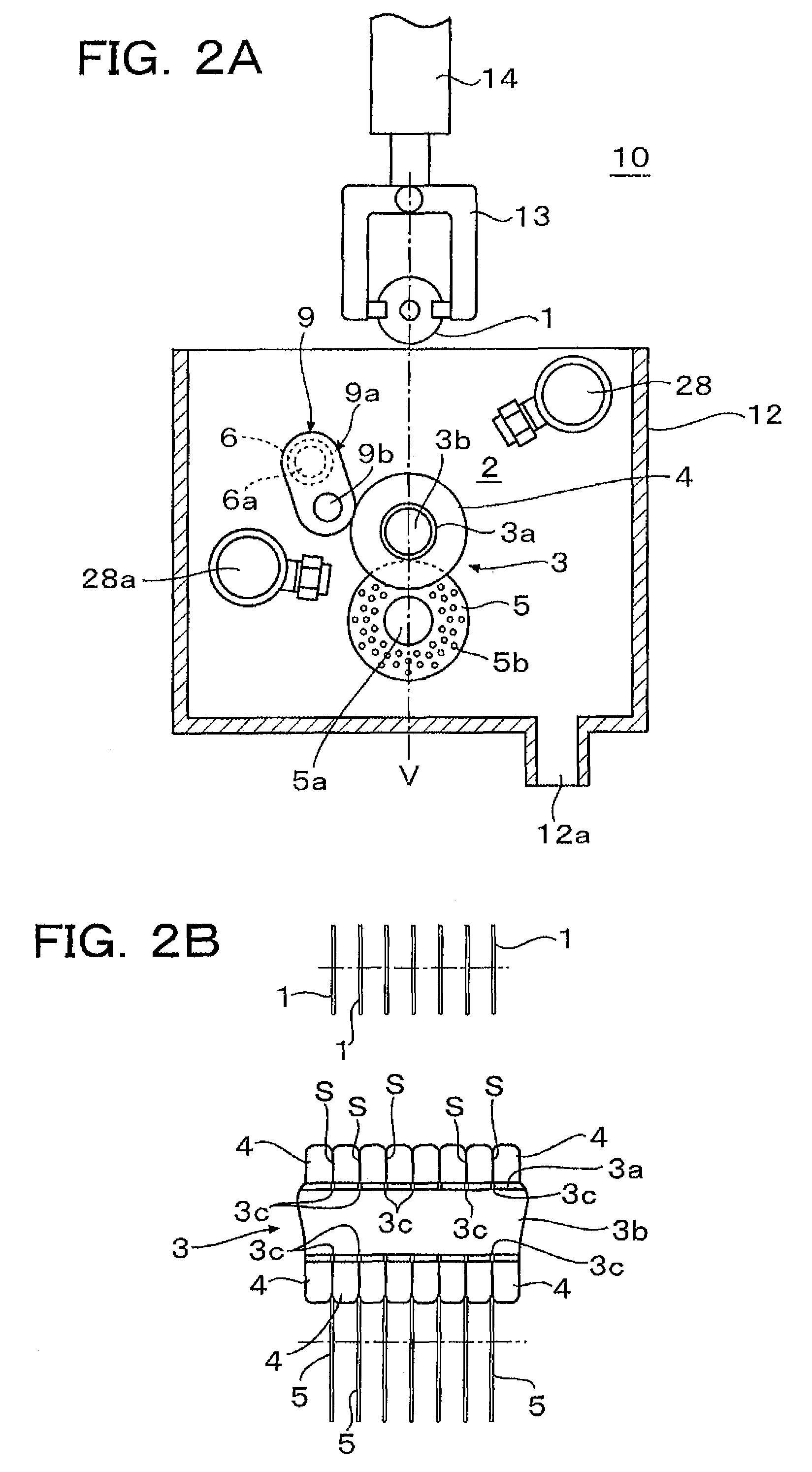
[0051]The roller 3a has a sleeve fixedly mounted on the rotary shaft 3b and the sleeve is rotated by rotation of the rotary shaft 3b. The roller 3a is constructed with the sleeve and the rotary shaft 3b. As shown in FIG. 2B, grooves 3c are formed on the sleeve of the roller 3a in contact positions S corresponding to portions with which surfaces of adjacent brushes 4 are in contact. The rotary shaft 3b rotates the discs 1 through frictional force due to rotation of the brushes 4 and the grooves 3c.

[0052]As shown in FIG. ...

embodiment 2

[0087]FIG. 5 shows another embodiment of the present invention in which the disc is chucked at three points of the outer periphery thereof.

[0088]As shown in FIG. 5A, this embodiment is featured by that the roller loading mechanism 9 is provided as a 3-point chucking mechanism.

[0089]That is, in the roller loading mechanism 9, the roller 3a is used as one of three chucking shafts and the disc revolution stopper 6 is used as one of the remaining two chucking shafts. Further, as shown in FIG. 5A, the last chucking shaft is a guide roller 7 having a structure similar to that of the disc revolution stopper 6. Incidentally, a reference numeral 7a is a rotary shaft of the guide roller 7.

[0090]The guide roller 7 is arranged on an opposite side to the disc revolution stopper 6 about the vertical line V, as shown in FIG. 5B. The roller 7 has no revolution stopping function as that of the disc revolution stopper 6 and only guides the rotation of the discs. In order to explain the principle of 3...

embodiment 3

[0097]FIG. 6 is a side cross section of a disc cleaning device according to another embodiment of the present invention.

[0098]In FIG. 6, a reference numeral 20 depicts a disc cleaning device, 20a a base casing and 20b an upper cover.

[0099]A reference numeral 1 depicts discs to be cleaned, 21 a disc loading mechanism and 22 a disc receiving mechanism. Reference numerals 23 and 24 depict rotary brush units and reference numerals 51 and 52 depict brush cleaner discs.

[0100]The disc loading mechanism 21 is provided on the load side adjacently to the rotary brush unit 23. The disc loading mechanism 21 inserts a plurality of discs 1 to the rotary brush unit 23 while the brushes are kept rotating.

[0101]The disc loading mechanism 22 is provided on the unload side adjacently to the rotary brush unit 24. The disc loading mechanism 22 receives a plurality of cleaned discs 1 from the rotary brush unit 24 and ejects them externally of the device. This disc receiving mechanism can receive the disc...


PUM


Abstract

A disc cleaning mechanism or device has a rotary brush having a rotary shaft on which a plurality of brushes are mounted and, between adjacent brushes of which a plurality of discs is inserted, and a disc revolution stopper for preventing the discs inserted between the brushes from revolving about the rotary shaft by rotation of the rotary brush and allowing the discs to rotate. The disc cleaning mechanism includes a core roller having an uneven inner peripheral portion of the brush as a core of the brush and an uneven outer peripheral portion and a rotary shaft on which a plurality of the core rollers are mounted. The brush and the core rollers constitute a spline joint.

Description

TECHNICAL FIELD[0001]This invention relates to a disc cleaning machine, a disc cleaner thereof and a rotary brush thereof and, particularly, in a disc cleaner for scrubbing a disc such as a wafer, hard disc or optical disc, this invention relates to a disc cleaning machine, with which a batch of discs can be scrubbed simultaneously, throughput of cleaning can be improved and the size thereof can be minimized.BACKGROUND ART[0002]A substrate of, for example, a hard disc, is scrubbed after steps of grinding, polishing, sputtering and plating, etc. On the other hand, the cleaning of such as wafer includes a plurality of cleaning steps and a corresponding number of drying steps.[0003]In a known scrubbing device, the scrubbing step is performed by dipping a carrier (or a tray), on which a plurality of discs are vertically mounted, in a tab filled with cleaning agent and applying ultra sonic waves thereto. In such a case, the cleaned discs are dried by transporting the carrier (or tray) in...

Claims


Application Information

Patent Timeline
Patent Type & Authority Patents(United States)
IPC IPC(8): B08B11/02
CPCA46B5/0012B08B1/04H01L21/67046A46B11/0006A46B13/008
Inventor SHIZAWA, NORITAKESHIRAISHI, TOSHIMITSUKANEKO, TATSUO
Owner HITACHI HIGH-TECH CORP
Why Eureka
Try Eureka