Lamb wave resonator

a resonator and lamb wave technology, applied in the field of resonators, can solve the problems of difficult to obtain the difference in piezoelectric layer propagation coefficient, filter limitations, saw device propagation loss, etc., and achieve the effect of effectively using the resonance energy of lamb waves, low series resistance, and high quality factor

Active Publication Date: 2011-01-11
CENT NAT DE LA RECHERCHE SCI +1
View PDF21 Cites 20 Cited by
  • Summary
  • Abstract
  • Description
  • Claims
  • Application Information

AI Technical Summary

Benefits of technology

[0008]In view of the foregoing background, an object of the present invention is to provide a Lamb wave resonator of which the shape makes it possible to effectively use the resonance energy of the Lamb waves, while having a high quality factor and a low series resistance by comparison with known resonators, and the production of which may not require a specific step of treating the piezoelectric layer.
[0016]Thus, with such a resonator comprising fingers of which the width W is thus calculated, the resonance energy of the Lamb waves generated in the resonator is best used. Moreover, the quality factor may thus be increased and the series resistance of the resonator may be reduced with respect to the known devices.
[0017]Such a resonator with a high quality factor makes it possible, in particular, to produce voltage control oscillators with a very low phase noise and low consumption, intermediate frequency filters (between about 10 MHz and 200 MHz) with low insertion losses and high selectivity, and band-pass sigma-delta modulators with a very high rejection and very low consumption. In general, these advantages are found in any type of device using at least one such resonator in the intermediate frequency band.
[0018]In addition, the density of the piezoelectric material may be reduced at the level of the inactive zones of the resonator located between the fingers of the first electrode by at least partial etching of portions of the piezoelectric layer located between the fingers of the first electrode. These etched portions may create a discontinuity of the conditions for acoustic propagation between the active zones of the piezoelectric layer located at the level of the fingers of the first electrode, and the inactive zones of the piezoelectric layer located between the fingers of the first electrode. This discontinuity may modify the acoustic transmission parameters in the piezoelectric layer, thus making it possible to confine the acoustic resonance energy in the active zone(s) of the resonator.

Problems solved by technology

However, these filters have limitations.
The maximum resonance frequencies are generally equal to about 3 GHz, and the maximum power handling is equal to about 1 W. Outside of this range of operation, SAW devices have significant propagation losses.
This difference with regard to the propagation coefficient in the piezoelectric layer is difficult to obtain and requires specific steps of treating the piezoelectric layer.
These resonators have, in particular, the disadvantages of having a relatively low quality factor and a high series resistance.

Method used


Image

  • Lamb wave resonator
  • Lamb wave resonator
  • Lamb wave resonator

Examples


Embodiment Construction

[0040]Identical, similar or equivalent parts of the various figures described below have the same numeric references for consistency between the figures. The various parts shown in the figures are not necessarily shown according to the same scale, so as to make the figures easier to read. The various possibilities (alternatives and embodiments) are to understood as being non-exclusive of one another, and can be combined with one another.

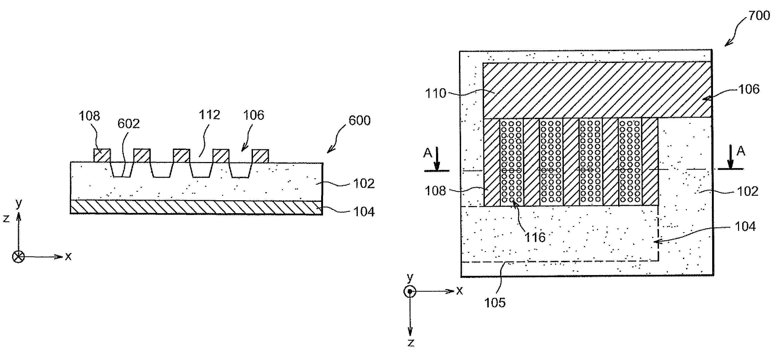
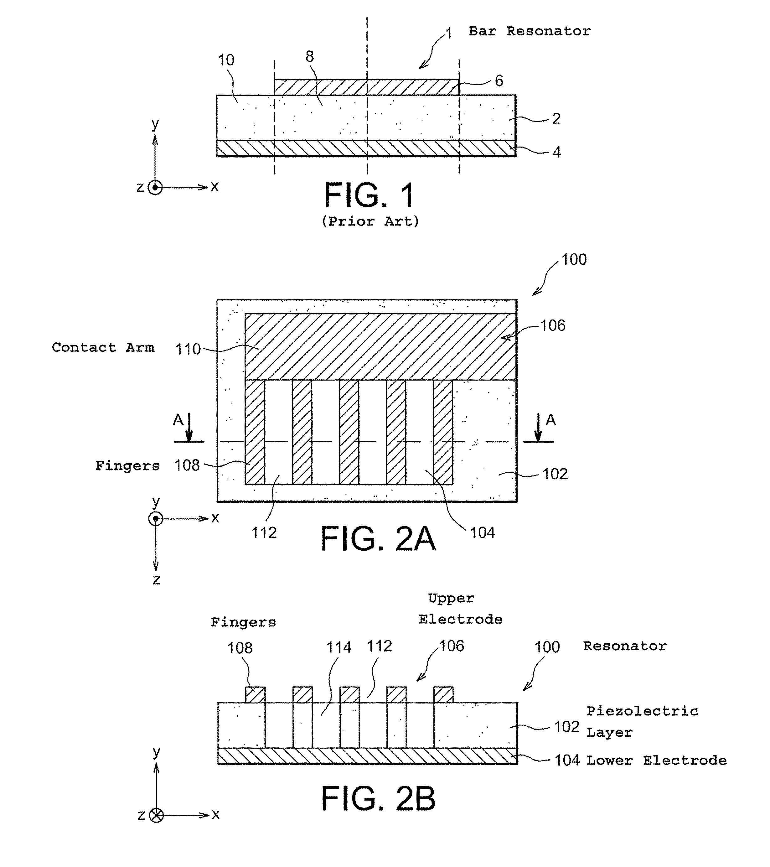
[0041]Reference is first made to FIGS. 2A and 2B, which respectively show a top view and a cross-section view according to axis AA as shown in FIG. 2A, of a Lamb wave resonator 100 according to a first embodiment.

[0042]This resonator 100 comprises a layer 102 based on a piezoelectric material. Preferably, this piezoelectric material is aluminum nitride and / or zinc oxide and / or PZT. The piezoelectric layer 102 has a thickness of which the value is dependent on the embodiments as well as the shape and dimensions of the other elements of the resonator 1...


PUM


Abstract

A Lamb wave resonator includes a piezoelectric layer, and a first electrode against a first face of the piezoelectric layer. The first electrode includes fingers and a contact arm, with each finger including a first side in contact with the contact arm and two other sides parallel to one another. Portions of the piezoelectric layer are at least partially etched between the two fingers to form a recess. The fingers are spaced apart from one another by a distance W calculated according to the following equation:W=n·valateralf,with⁢⁢n∈Nwhere,valateral is an acoustic propagation speed of Lamb waves,n is an order of a resonance mode of the Lamb waves,f is a resonance frequency of the Lamb wave resonator.

Description

FIELD OF THE INVENTION[0001]The present invention relates to the field of resonators, as well as to the field of filters obtained from Lamb wave resonators. These filters may be used in RF (radio frequency) transmission and / or reception structures, such as mobile communication devices, to perform channel filtering or intermediate frequency filtering, for example.BACKGROUND OF THE INVENTION[0002]To perform RF filtering, SAW (surface acoustic wave) filters may be used, which are produced by coupled SAW resonators. Typically, for such a filter with dimensions equal to about 3 mm×3 mm×1 mm, the insertion losses can be between 2.5 dB and 3 dB with a rejection equal to about 30 dB. However, these filters have limitations. The maximum resonance frequencies are generally equal to about 3 GHz, and the maximum power handling is equal to about 1 W. Outside of this range of operation, SAW devices have significant propagation losses.[0003]BAW (bulk acoustic wave) filters may be produced from pie...

Claims


Application Information

Patent Timeline
Patent Type & Authority Patents(United States)
IPC IPC(8): H01L41/04
CPCH03H9/17H03H9/02228
Inventor BELOT, DIDIERCATHELIN, ANDREIASHIRAKAWA, ALEXANDRE AUGUSTOPHAM, JEAN-MARIEJARY, PIERREKERHERVE, ERIC
Owner CENT NAT DE LA RECHERCHE SCI
Why Eureka
Try Eureka