Image forming apparatus

a technology of image forming apparatus and photoconductive member, which is applied in the direction of electrographic process apparatus, instruments, optics, etc., can solve the problems of less durable developing roller and supply roller, large and complicated development device, and increased consumable cost, so as to improve the developability of the photoconductive member, suppress image defects, and facilitate balan

Active Publication Date: 2011-05-10
KYOCERA DOCUMENT SOLUTIONS INC
View PDF17 Cites 5 Cited by
  • Summary
  • Abstract
  • Description
  • Claims
  • Application Information

AI Technical Summary

Benefits of technology

[0016]An object of the present invention is to enable an easy balance between a bias formed between a developing roller and a photoconductive member and the one formed between the developing roller and a magnetic roller. Another object is to satisfactorily form a thin toner layer on the developing roller and collect the toner from the developing roller, to improve developability on the photoconductive member and to suppress image defects such as the image nonuniformity of low tone images.

Problems solved by technology

The two-component developing method has advantages of having a good chargeability of the toner by the carrier and a longer operating life, whereas it has disadvantages of making a developing device large and complicated and varying image quality depending on the durability of the carrier.
Further, the one-component developing method has advantages of making the developing device compact and having a good dot reproducibility, whereas it has disadvantages of generally making a developing roller and a supply roller less durable and making a consumable cost more expensive due to the exchange of developing devices on a regular basis.
Further, the supply of the toner having such a charging property as to be developed on the developing roller is not suitable for high-speed processing apparatuses, which has presented a problem to the speed-up of the image formation.
Thus, if developing rollers and magnetic rollers are transversely arranged with respect to photoconductive members, the electrophotographic processing members themselves have a large width, which hinders the miniaturization.
However, according to this method, a toner charge control is complicated and it is necessary to apply a high surface potential and a large developing electric field to a photoconductive member.
Further, it is difficult to refresh the toner on the donor roller, which was not used for development, and a toner adhering state and a potential difference of the toner on the donor roller vary if a toner consumed region and a toner non-consumed region are present on the donor roller.
Therefore, there has been a demand for technology requiring less control accuracy.
In this device, an alternating-current voltage is applied to the developing roller, thereby preventing a problem that it is difficult to develop low-density images and thin line images and a problem that density nonuniformity occurs due to an increase in a toner charge amount and making it easier to scrape off (collect) the toner not having been used for development.
However, an image fog occurs if the alternating-current voltage applied to the developing roller for forming a developing electric field is increased, whereas the effect of scraping off the toner not having been used for development is reduced if the alternating-current voltage is decreased.
However, the developing device is of the type using the one-component developer and constructed such that the photoconductive member and the supply roller are in contact with the developing roller and, if the developing devices of such a type in which the photoconductive member and the developing roller are in contact are used in a tandem image forming apparatus, a torque variation of a transfer belt might be caused to promote a color drift as a weak point of the tandem image forming apparatus.
However, since the biases applied to the developing roller and the magnetic roller become a composite bias between the developing roller and the magnetic roller, the bias applicable to suppress a discharge while maintaining the developability and collectability is restricted in its phase, cycle and waveform, which has hindered the miniaturization and the higher speed.
This, for example, hinders the toner supply from the developing roller to the photoconductive member and makes it difficult to collect the toner from the developing roller to the magnetic roller.
With the technologies of the patent literatures described above, it has been difficult to balance the bias formed between the developing roller and the photoconductive member and the one formed between the developing roller and the magnetic roller to improve the developability on the photoconductive member while coping with the formation of the thin toner layer on the developing roller and the collection of the toner from the developing roller in the development process asking for the faster rotation and the smaller diameter of the photoconductive member and the smaller toner particles.
There has been also a problem that the image nonuniformity of low tone images occurs due to the deterioration of the developer and the variation of the nip width between the developing roller and the photoconductive member caused by the repeated phenomenon.

Method used


Image

  • Image forming apparatus
  • Image forming apparatus
  • Image forming apparatus

Examples


Embodiment Construction

[0030]One embodiment of the present invention is described below with reference to the accompanying drawings, but the present invention is not limited to this embodiment. The embodiment of the present invention is a most preferable mode of the invention and the application thereof and terms and the like used here are not limited thereto.

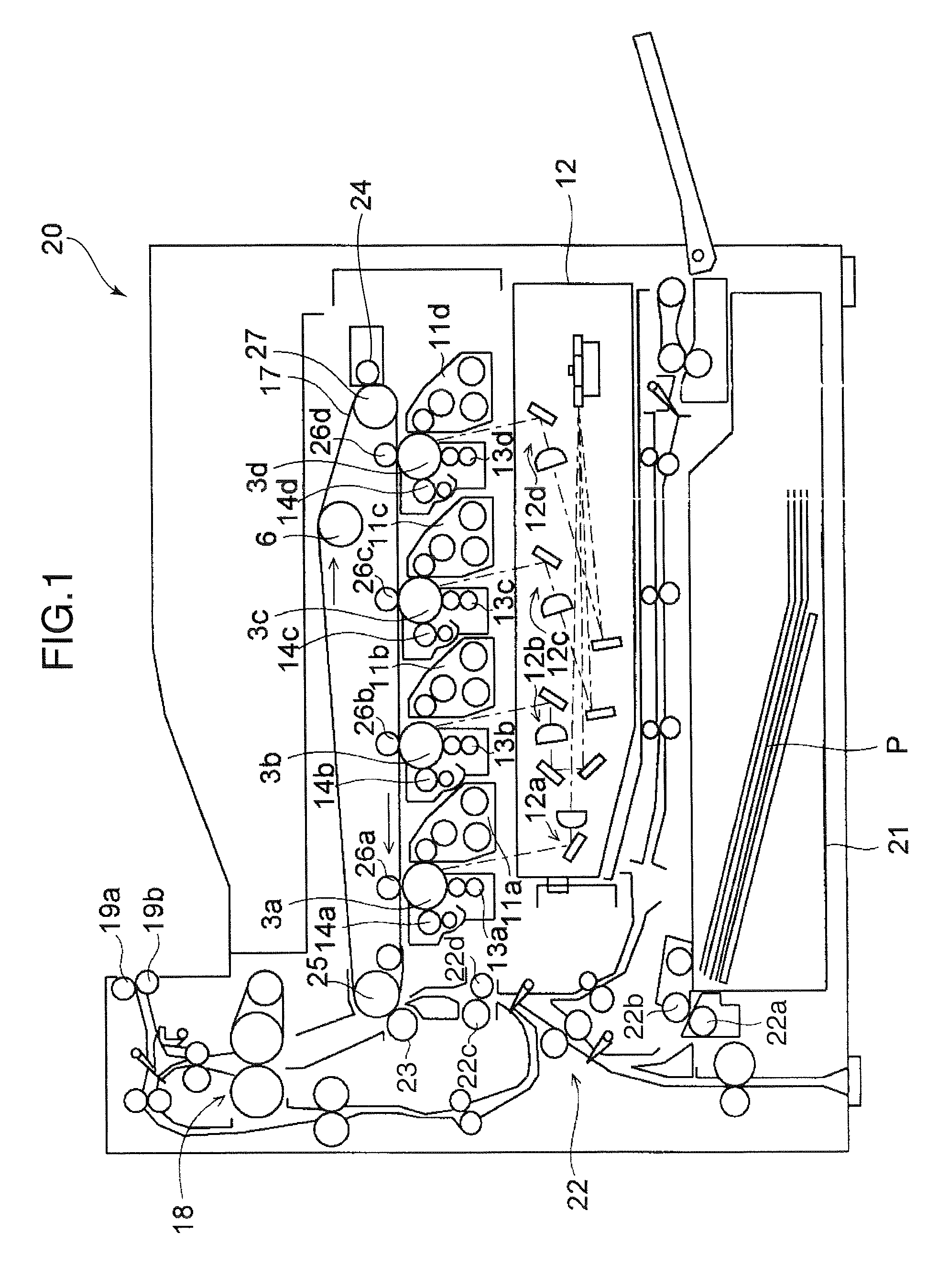
[0031]FIG. 1 is a schematic diagram showing the entire construction of an image forming apparatus 20 according to one embodiment of the present invention. The image forming apparatus 20 includes rotatable photoconductive members 3a to 3d provided in correspondence with the respective colors of black (B), yellow (Y), cyan (C) and magenta (M). An amorphous silicon photoconductor or an organic photoconductor (OPC) is, for example, used as a photoconductive material for forming photoconductive layers of the photoconductive members 3a to 3d.

[0032]A developing device 11a to 11d, an optical exposure device 12a to 12d, a charger 13a to 13d and a cleaning de...


PUM


Abstract

An image forming apparatus is provided with a photoconductive member on which a latent image is to be formed, a developing roller for developing the latent image formed on the photoconductive member by a first bias, and a magnetic roller for forming a magnetic brush thereon with a two-component developer and forming a thin toner layer on the developing roller by a second bias. If (D1) denotes the duty ratio of a first alternating-current bias included in the first bias and (D2) denotes the duty ratio of a second alternating-current bias included in the second bias, the duty ratios (D1, D2) satisfy the following relationship:D1>100−D2.

Description

BACKGROUND OF THE INVENTION[0001]1. Field of the Invention[0002]The present invention relates to an electrophotographic image forming apparatus using a two-component developer containing a magnetic carrier and a nonmagnetic toner.[0003]2. Description of the Related Art[0004]A two-component developing method using a toner and a carrier and a one-component developing method using no carrier are known as developing methods in image forming apparatuses. The two-component developing method has advantages of having a good chargeability of the toner by the carrier and a longer operating life, whereas it has disadvantages of making a developing device large and complicated and varying image quality depending on the durability of the carrier. Further, the one-component developing method has advantages of making the developing device compact and having a good dot reproducibility, whereas it has disadvantages of generally making a developing roller and a supply roller less durable and making a...

Claims


Application Information

Patent Timeline
Patent Type & Authority Patents(United States)
IPC IPC(8): G03G15/06G03G13/09G03G15/09
CPCG03G15/0907
Inventor SAKATA, SHOICHINAKAUE, TAKAHISAKOBAYASHI, KIYOTAKAMORI, YUKIHIRO
Owner KYOCERA DOCUMENT SOLUTIONS INC
Why Eureka
Try Eureka