Double-duty, hold-down system

a technology of holding down and holding down, applied in the field of building construction, can solve the problems of sacrificing building anchoring capacity, affecting so as to reduce hardware, reduce the effect of sacrificing the ability of building anchoring

Inactive Publication Date: 2011-07-05
COMMINS ALFRED D
View PDF7 Cites 40 Cited by
  • Summary
  • Abstract
  • Description
  • Claims
  • Application Information

AI Technical Summary

Benefits of technology

[0014]In accordance with the foregoing, certain embodiments of an apparatus, system, and method in accordance with the invention provide a continuous hold-down system useful for multi-story applications, that is easily and quickly installed. The hardware involved with the foregoing systems, apparatus, and methods may be mass produced and installed comparatively inexpensively.
[0018]At the held locations, take-up units may act as extensible washers between a station therebelow and a fastener thereabove. The fastener secures to the rod, capturing the take-up unit below it, on top of an anchoring station. Thus the take-up devices help maintain tension throughout the system, essentially removing subsequent slack arising in the securement system anchoring the entire structure to the foundation. Securing the structure to the foundation without slack, and taking up future slack, enables the structure to better withstand various forces acting on the structure. These forces are transferred to the foundation where they can be dissipated more efficiently.
[0021]Instead of such solutions, the apparatus, systems, and methods in accordance with the invention, using a continuous rod, allow reduced hardware without sacrificing building anchoring capacity. Meanwhile, when provided with take-up devices, the system may compensate for shrinkage or crushing occurring on any level of the building. Thus, if shrinkage or crushing on one level exceeds the capacity of the system on that level, the system on other levels can compensate for the excess.
[0022]The system may also take advantage of unique, take-up units. Individual take-up units may be stackable, providing greater ability to compensate for abnormally large amounts of shrinkage and crushing. This is especially helpful in compensating for shrinkage and crushing as the number of levels increases for any building design. Therefore, if one of the upper levels of the building has one or more extra take-up units stacked, those units can compensate for any excess shrinkage or crushing throughout the building therebelow.

Problems solved by technology

Strong winds and earthquakes subject walls and others elements of a building to tremendous forces.
If these forces are not distributed to the proper elements or structures capable of withstanding such force, the building may be torn apart.
Securement promotes single body motion limiting whiplash amplification otherwise often resulting in structural failure.
Tall narrow shear walls, which may be found in nearly all homes, act as lever arms and may magnify an imposed load.
However, lower levels can present amplification of structural weaknesses to upper levels.
If a hold-down system installed on a given level cannot compensate for all shrinkage and crushing affecting that level, structural weaknesses may be amplified on adjacent levels.
Moreover, hold-down systems can be difficult to install and expensive to fabricate.
Some hold-down systems require assembly within narrow tolerances, making assembly difficult and time consuming.
Other hold-down systems cannot compensate for structural weaknesses throughout the structure, causing an overload of a hold-down system on a given level.
Some systems by major suppliers, when applied to multi-story buildings may accumulate slack with each floor.
Thus, at all points between the discreet locking points, such systems, leave a certain amount of slack, greatly compromising their effectiveness.
Thus, the additive cost may be substantial for the numerous locations in a building warranting placement of hold-downs.

Method used


Image

  • Double-duty, hold-down system
  • Double-duty, hold-down system
  • Double-duty, hold-down system

Examples


Embodiment Construction

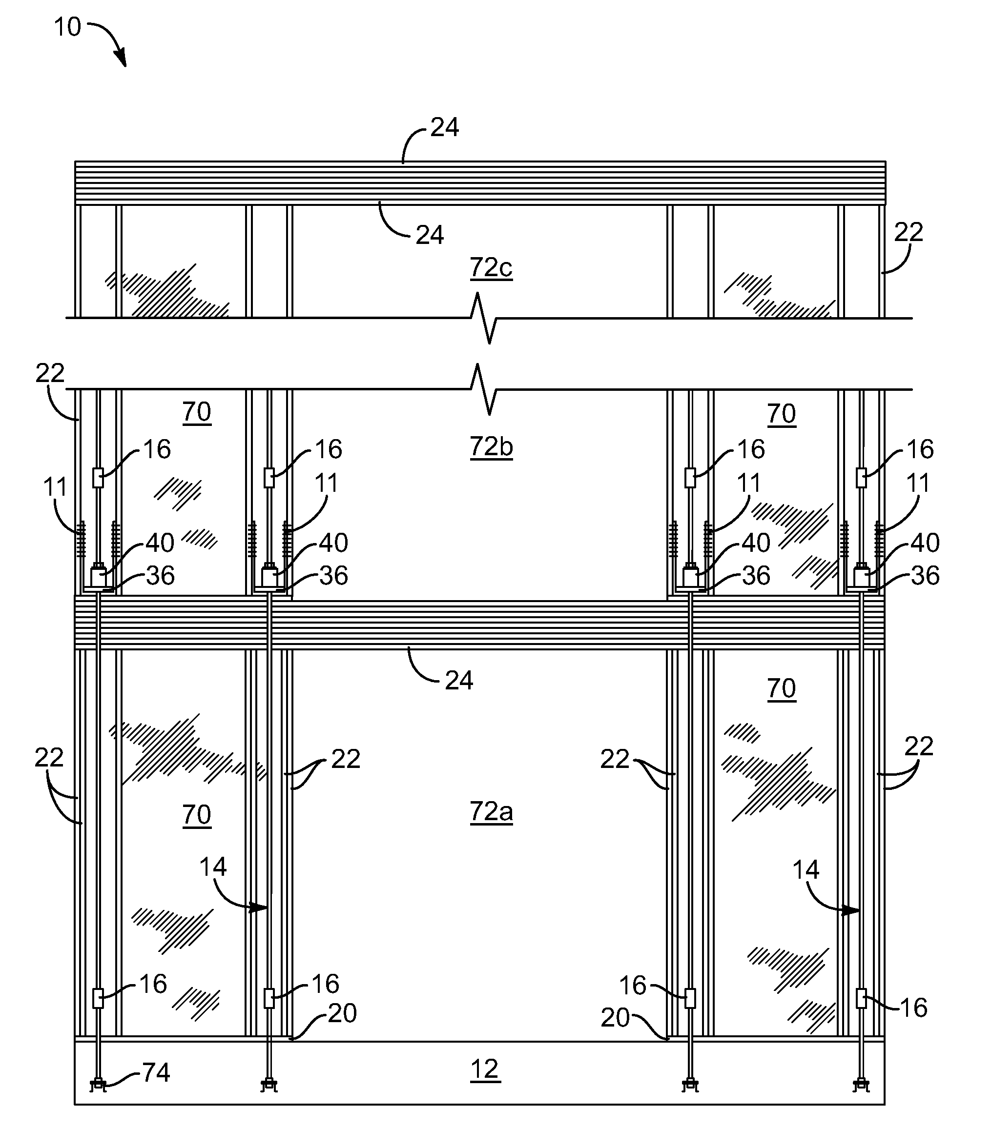
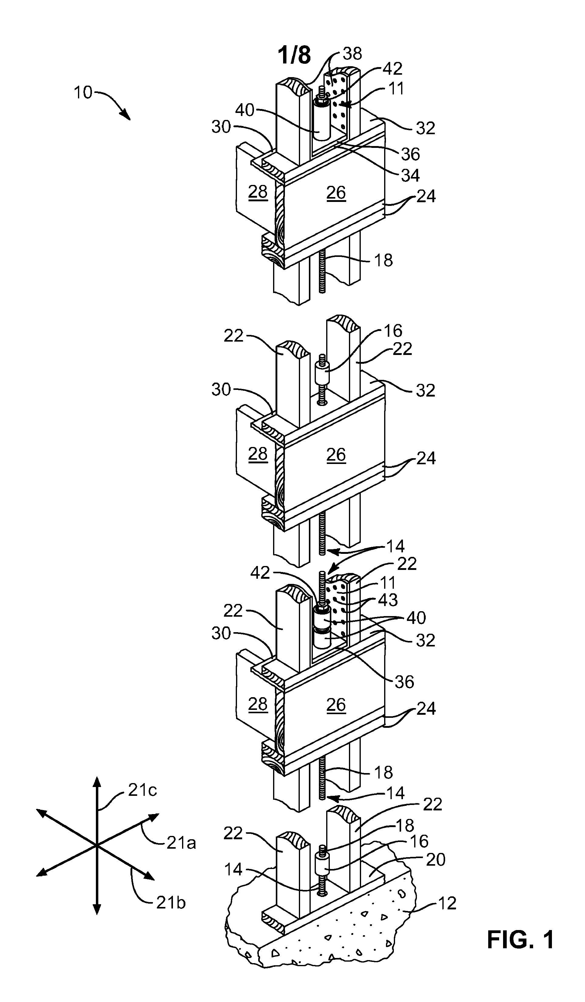
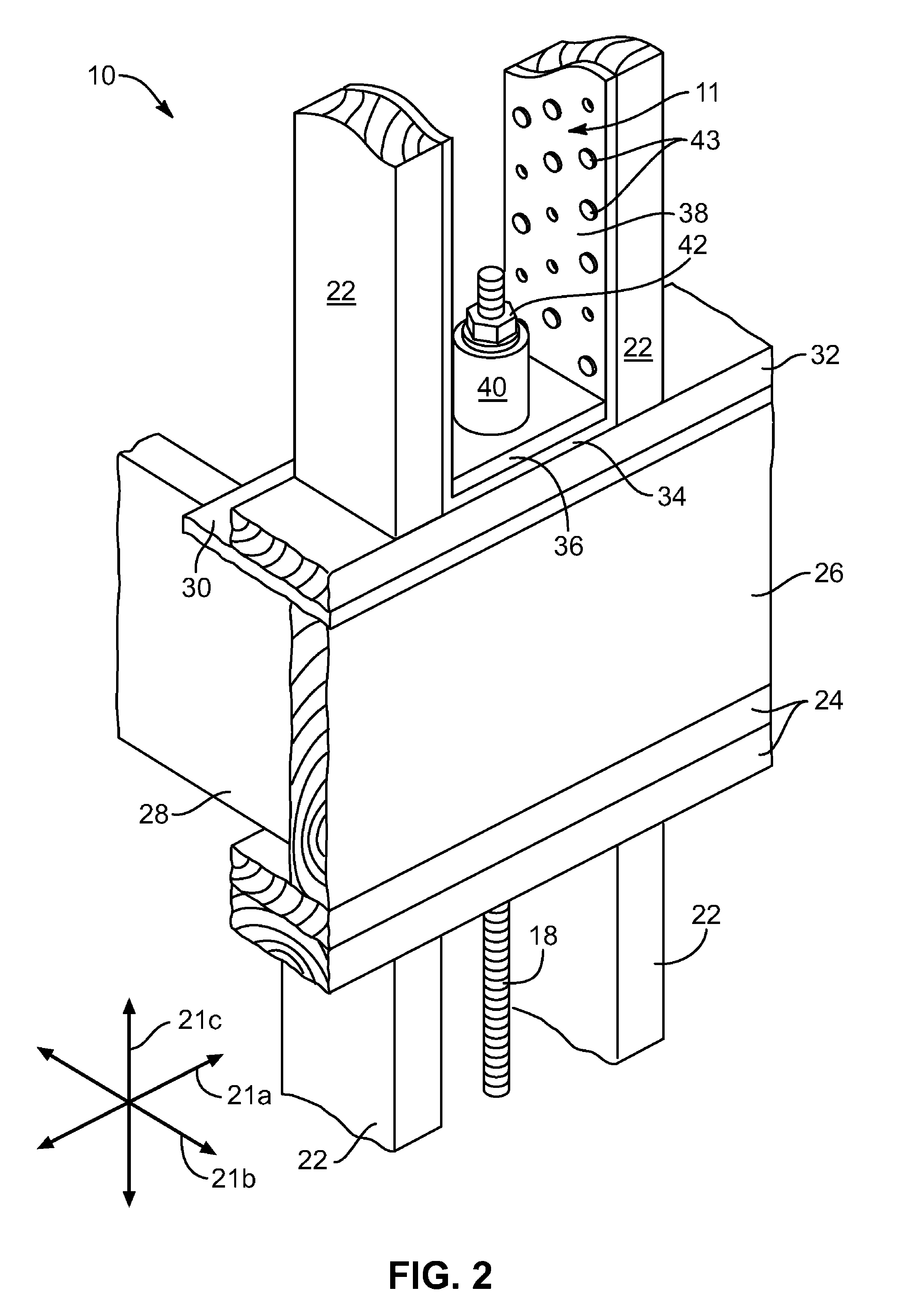
[0033]Referring generally to FIGS. 1-8, those of ordinary skill in the art will, of course, appreciate that various modifications to the details of the Figures may easily be made without departing from the essential characteristics of the invention. Thus, the following description of the Figures is intended only by way of example, to simply illustrate certain embodiments consistent with the invention, and is not intended to limit the scope of the invention.

[0034]The scope of the invention is as broad as claimed herein. The illustrations are merely representative of certain, illustrative embodiments of the invention. Those embodiments of the invention will be best understood by reference to the drawings, wherein like parts are designated by like numerals throughout. A trailing letter after a reference numeral in the Figures simply indicates a specific instance of the item otherwise indicated by the reference numeral.

[0035]Several Figures display an automatic take-up unit. This device...


PUM


Abstract

A method for securing a building to a foundation provides hold-down units that perform double-duty by acting as a compressive load on a floor immediately therebelow due to the force of a seat or base portion thereof. Meanwhile, a flange portion of each hold-down device extends upward to fasten to the upright members in an upper floor applying tension thereto. Thus, an anchoring rod extending through multiple floors of the shear walls may reduce the number of total hold-down devices by an amount approaching half that otherwise required. Likewise, the number of more expensive, automatic, take-up devices used is reduced by approximately half.

Description

RELATED APPLICATIONS[0001]This application claims the benefit of co-pending U.S. Provisional Patent Application Ser. No. 60 / 982,372, filed on Oct. 24, 2007.BACKGROUND[0002]1. Field of the Invention[0003]The present invention relates to building construction, and more specifically, to apparatus for anchoring shear walls to foundations and lower floors.[0004]2. Background[0005]Strong winds and earthquakes subject walls and others elements of a building to tremendous forces. If these forces are not distributed to the proper elements or structures capable of withstanding such force, the building may be torn apart. Foundations are often the strongest element of a building. Securely tying the walls of a building to the foundation greatly improves structural performance during periods of strong wind or earthquake. Securement promotes single body motion limiting whiplash amplification otherwise often resulting in structural failure.[0006]Under extreme conditions, a building may be violently...

Claims


Application Information

Patent Timeline
Patent Type & Authority Patents(United States)
IPC IPC(8): E04H12/00E02D27/00
CPCE04B1/2604E04B2001/2684E04B2001/3583E04H9/14Y02A50/00
Inventor COMMINS, ALFRED D.
Owner COMMINS ALFRED D
Why Eureka
Try Eureka