Method for operating fuel-cell electricity-generating device

a technology of electricity generation device and fuel cell, which is applied in the direction of electrochemical generators, fuel cells, electrical apparatus, etc., can solve the problems of deteriorating the durability the suspension of the operation of the fuel cell electricity generation device, so as to prevent abnormal rise of the temperature of the fuel processor, deterioration of durability or damage of the fuel processor

Inactive Publication Date: 2011-09-06
PANASONIC CORP
View PDF15 Cites 2 Cited by
  • Summary
  • Abstract
  • Description
  • Claims
  • Application Information

AI Technical Summary

Benefits of technology

[0015]An object of the present invention is to provide a fuel cell electricity-generating device, and a fuel cell electricity-generating method which are not subject to abnormal rise of the temperature of the fuel processor and hence deterioration of the durability or damage of the fuel processor even if the load power shows sudden drop taking into account these problems of the prior art fuel cell electricity-generating device.
[0047]Thus, in the present invention, the generated electric power determined by the electric power generation instructing means of determining the electric power generated by the fuel cell is limited depending on the temperature of the fuel producing means of the fuel processor of producing a fuel to be supplied into the aforementioned fuel cell from an electricity-generating material, preventing abnormal rise of the temperature of the fuel processor even in the case of sudden drop of load power and hence the deterioration of durability or damage of the fuel processor.

Problems solved by technology

However, when the generated electric power is suddenly decreased to increase the amount of the residual fuel gas to be discharged from the fuel cell as mentioned above, the residual fuel gas is then supplied into the combustion device 3 to suddenly increase the amount of combustion in the combustion device 3 in a short period of time, causing abnormal rise of the temperature of the fuel processor 2 that makes it necessary that the operation of the fuel cell electricity-generating device be suspended.
This not only deteriorates the durability of the fuel processor 2 but also leads to the damage of the fuel processor 2 in the worst case.

Method used


Image

  • Method for operating fuel-cell electricity-generating device
  • Method for operating fuel-cell electricity-generating device
  • Method for operating fuel-cell electricity-generating device

Examples


first embodiment

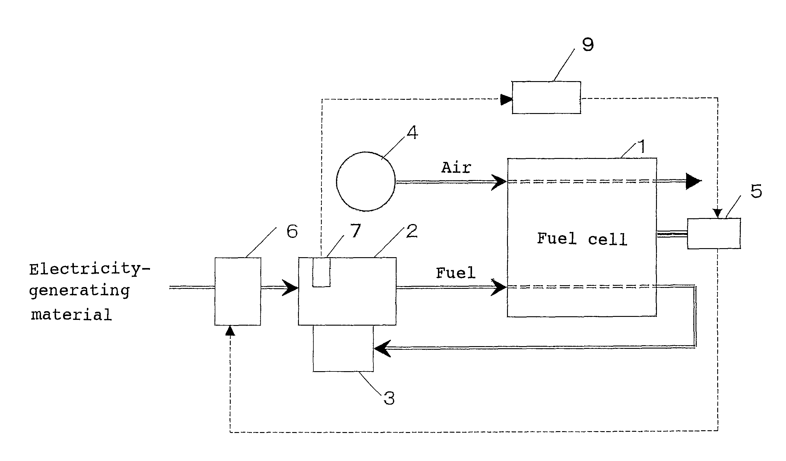
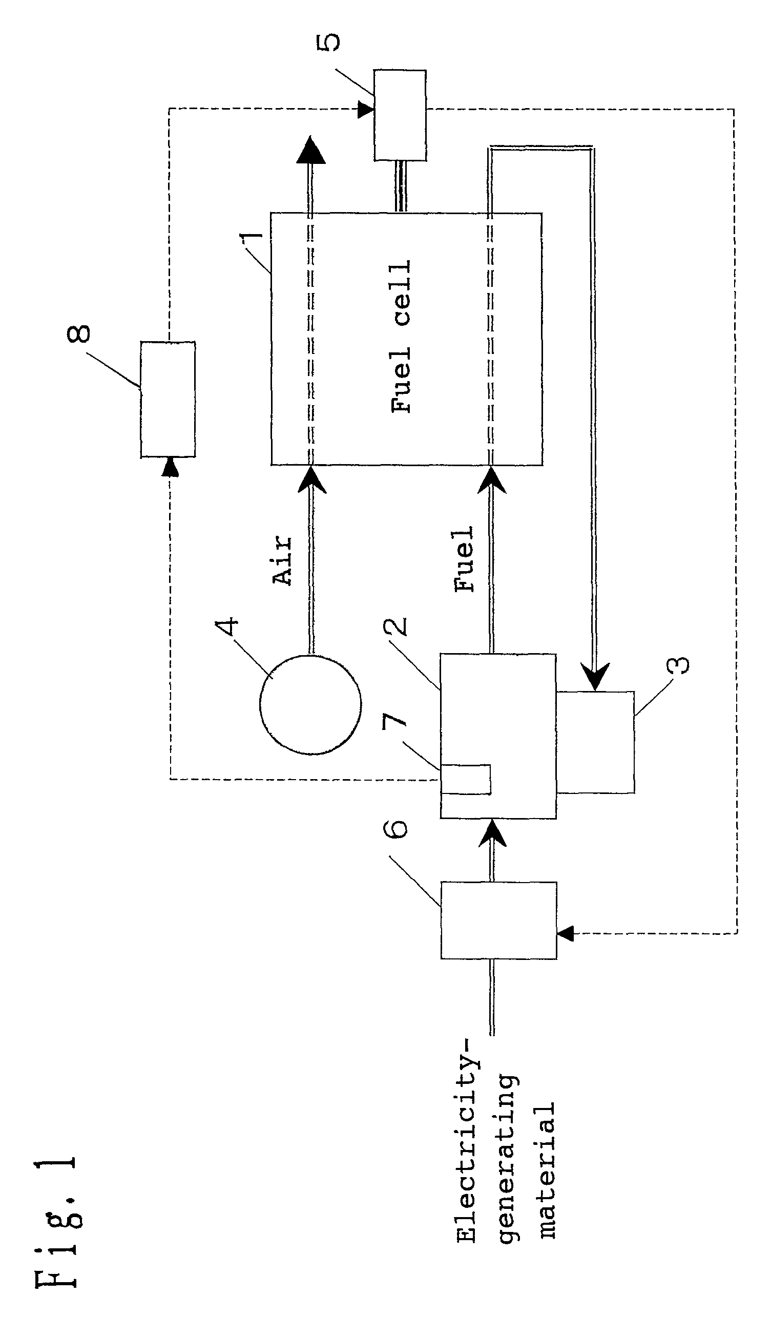
[0066]FIG. 1 illustrates one of embodiments of implementation of the present invention. Where the constituent elements are the same as those of the prior art example, the same numbers are used.

[0067]The fuel cell electricity-generating device according to an embodiment of implementation of the present invention has a fuel cell 1 of generating electricity with a fuel gas and an oxidizer, a fuel processor 2 of producing a fuel rich in hydrogen from an electricity-generating material comprising water incorporated in a natural gas or the like, a combustion device 3 of combusting a residual fuel gas discharged from the fuel cell 1, a blower 4 of supplying air into the fuel cell 1 as an oxidizer, an electric power generation instructing means 5 of adjusting the electric power generated by the fuel cell 1, an electricity-generating material adjusting device 6 of adjusting the amount of electricity-generating material and water to be supplied into the fuel processor 2, a temperature sensing...

second embodiment

[0079]Next, the second embodiment of implementation of the present invention will be described in connection with the drawings.

[0080]The configuration of the fuel cell system according to the second embodiment of implementation of the present invention is shown in FIG. 3. Where the parts are the same as those of the fuel cell system according to the first embodiment, the same numbers are used and their detailed description are omitted.

[0081]The fuel cell electricity-generating device according to the present invention has a fuel cell 1 of generating electricity with a fuel gas and an oxidizer, a fuel processor 2 of producing a fuel rich in hydrogen from an electricity-generating material comprising water incorporated in a natural gas or the like, a combustion device 3 of combusting a residual fuel gas discharged from the fuel cell 1, a blower 4 of supplying air into the fuel cell 1 as an oxidizer, an electric power generation instructing means 5 of adjusting the electric power gener...

third embodiment

[0098]Next, a third embodiment of implementation of the present invention will be described in connection with the drawings.

[0099]The configuration of the fuel cell system according to the third embodiment of implementation of the present invention is shown in FIG. 5. Where the parts are the same as those of the fuel cell system according to the first embodiment, the same numbers are used and their detailed description are omitted.

[0100]The fuel cell electricity-generating device according to the present invention has a fuel cell 1 of generating electricity with a fuel gas and an oxidizer, a fuel processor 2 of producing a fuel rich in hydrogen from an electricity-generating material comprising water incorporated in a natural gas or the like, a combustion device 3 of combusting a residual fuel gas discharged from the fuel cell 1, a blower 4 of supplying air into the fuel cell 1 as an oxidizer, an electric power generation instructing means 5 of adjusting the electric power generated...


PUM

PropertyMeasurementUnit
electric poweraaaaaaaaaa
temperatureaaaaaaaaaa

Abstract

A stable and high reliability fuel cell electricity-generating device capable of generating electricity even in the case of sudden drop of load power. A fuel cell generating electric power from a fuel and an oxidizer, a fuel processor producing fuel to be supplied into the fuel cell from an electricity-generating material, a combustion device combusting a residual fuel gas unconsumed in the fuel cell to raise the temperature of the fuel processor, and an electric power generation instructing means of determining the electric power generated by the fuel cell, wherein when the electric power generation instructing means decreases the electric power generated by the fuel cell depending on the decrease of load power to be supplied, the rate at which the generated electric power is decreased is made different depending on the change of the temperature of the fuel processor.

Description

[0001]This application is a continuation of U.S. patent application Ser. No. 10 / 500,274, now abandoned filed Jun. 28, 2004, which is a U.S. National Phase Application of PCT International Application PCT / JP2003 / 05983, filed May 14, 2003, the entire disclosures of which are incorporated herein by reference.TECHNICAL FIELD[0002]The present invention relates to a fuel cell electricity-generating device, and a fuel cell electricity-generating method which generate electricity using a fuel cell.BACKGROUND ART[0003]A prior art fuel cell electricity-generating device will be described hereinafter.[0004]As shown in FIG. 9, a prior art fuel cell electricity-generating device has a fuel cell 1 of generating electricity with a fuel gas and an oxidizer, a fuel processor 2 of producing a fuel rich in hydrogen from an electricity-generating material comprising water incorporated in a natural gas or the like, a combustion device 3 of combusting a residual fuel gas discharged from the fuel cell 1, ...

Claims


Application Information

Patent Timeline
Patent Type & Authority Patents(United States)
IPC IPC(8): H01M8/04
CPCH01M8/04022H01M8/04373H01M8/04619H01M8/0494H01M8/0612Y02E60/50H01M8/06H01M8/04
Inventor OZEKI, MASATAKANAKAMURA, AKINARIMIYAUCHI, SHINJI
Owner PANASONIC CORP
Why Eureka
Try Eureka