Method of completing a well using a retrievable inflow control device

a control device and inflow technology, applied in the direction of fluid removal, survey, borehole/well accessories, etc., can solve the problems of not being able to vary the choke size of the permanent mount icd, complex intelligent completions, and high cos

Inactive Publication Date: 2011-10-18
SCHLUMBERGER TECH CORP
View PDF42 Cites 25 Cited by
  • Summary
  • Abstract
  • Description
  • Claims
  • Application Information

AI Technical Summary

Problems solved by technology

Intelligent completions are generally complex and expensive.
However, it has not been possible to vary the choke size of the permanent mount ICD without pulling the completion out of the well.

Method used


Image

  • Method of completing a well using a retrievable inflow control device
  • Method of completing a well using a retrievable inflow control device
  • Method of completing a well using a retrievable inflow control device

Examples


Embodiment Construction

[0025]As used here, the terms “up” and “down”; “upper” and “lower”; “upwardly” and “downwardly”; “below” and “above”; and other similar terms indicating relative positions above or below a given point or element may be used in connection with some implementations of various technologies described herein. However, when applied to equipment and methods for use in wells that are deviated or horizontal, or when applied to equipment and methods that when arranged in a well are in a deviated or horizontal orientation, such terms may refer to a left to right, right to left, or other relationships as appropriate.

[0026]In the following description, numerous details are set forth to provide an understanding of the present invention. However, it will be understood by those skilled in the art that the present invention may be practiced without these details and that numerous variations or modifications from the described embodiments are possible.

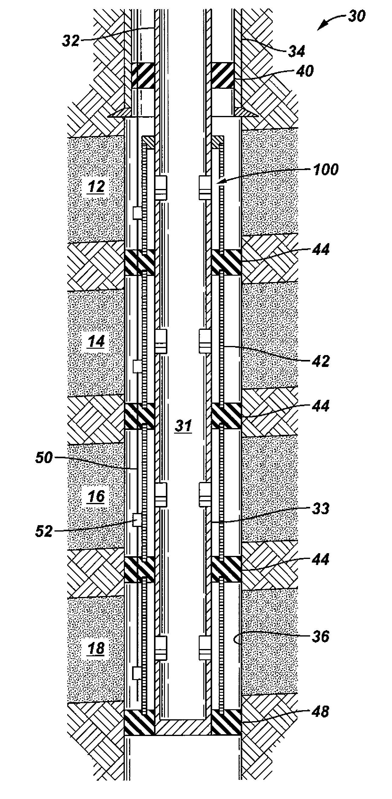
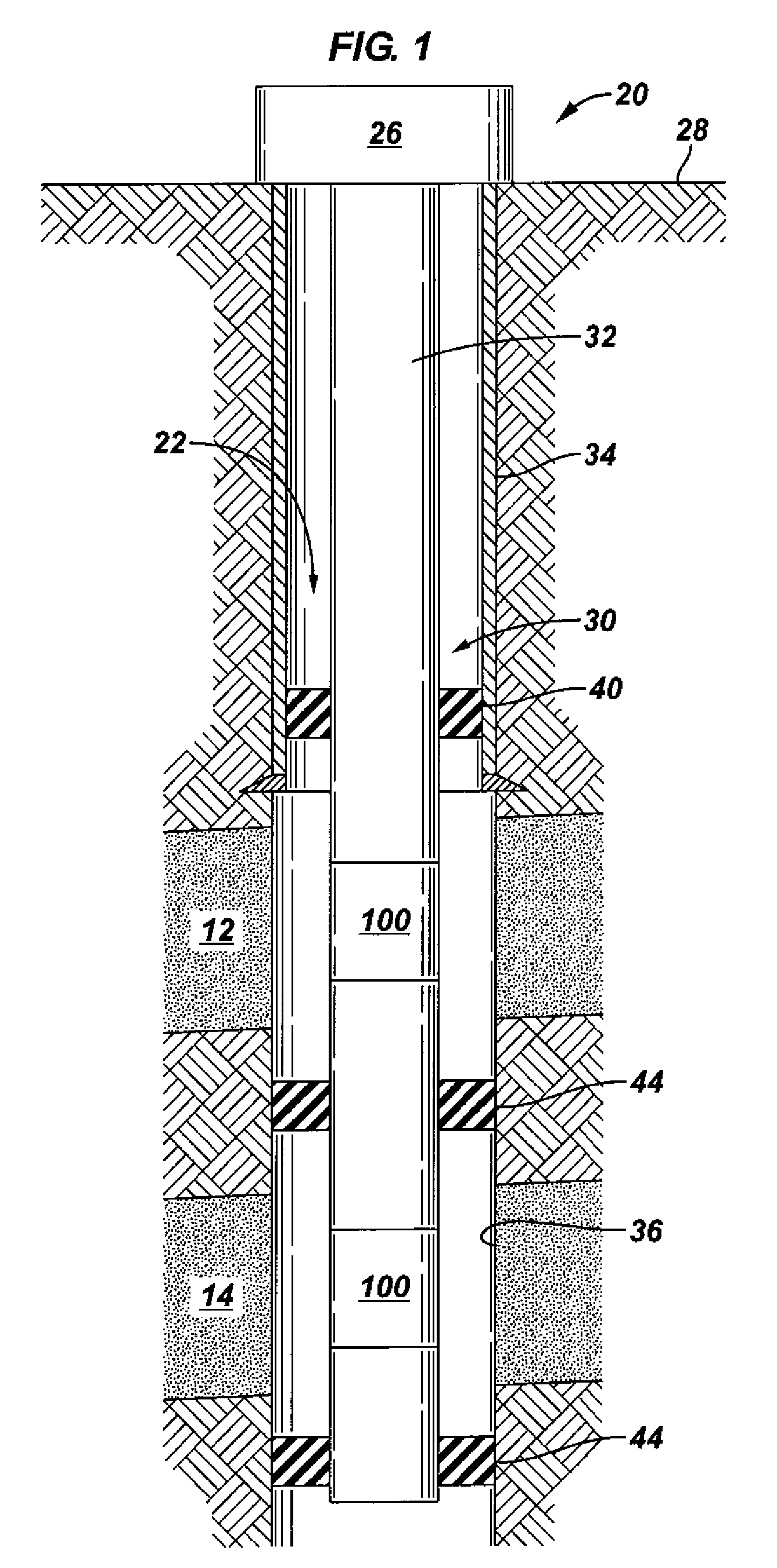
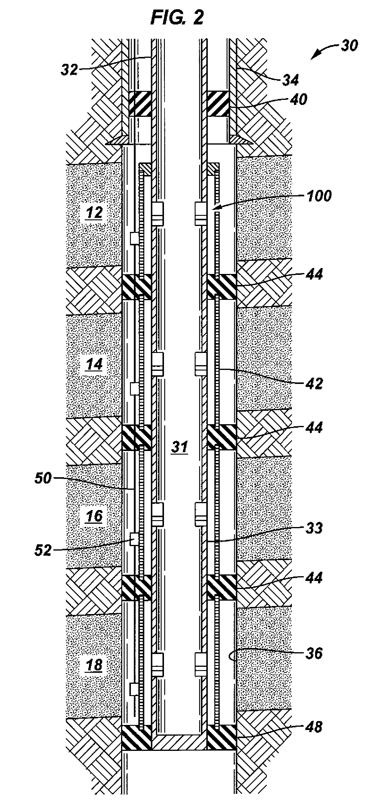
[0027]In accordance with an embodiment of the inv...


PUM


Abstract

A retrievable flow control device comprising a housing configured to sealably couple with a completion component. The housing may comprise a first port and a second port establishing a fluid pathway. The fluid pathway may regulate a fluid flow as the fluid flow passes through the fluid pathway. The housing may further comprise a coupling mechanism configured to releasably couple with a corresponding feature of the wellbore completion. The downhole flow control device may be configured to be retrievable independently of the completion component. The flow control device may comprise a check valve in the fluid pathway in order to substantially constrain the fluid flow to a single direction. In some cases, the flow control device may be configured to couple with a side pocket. In other cases, a concentric flow control device may be configured to couple with a screen base pipe, tubing, or stinger.

Description

RELATED APPLICATIONS[0001]This application claims the benefit of U.S. Provisional Application No. 60 / 970710, filed Sep. 7, 2007, the contents of which are incorporated herein.BACKGROUND[0002]1. Field of the Invention[0003]Embodiments of the present invention generally relate to inflow control devices used for producing hydrocarbon or injecting water with uniform flow across a reservoir, and more particularly to retrievable inflow control devices.[0004]2. Description of the Related Art[0005]The following descriptions and examples are not admitted to be prior art by virtue of their inclusion in this section.[0006]Intelligent flow control valves with variable chokes are typically run above the screen or inside of the screen for controlling the flow from each zone of interest. A hydraulic control line or an electric cable is run from the surface to the valve for operating the flow control valve. Intelligent completions are generally complex and expensive. Therefore, permanent mounted in...

Claims


Application Information

Patent Timeline
Patent Type & Authority Patents(United States)
IPC IPC(8): E21B34/08
CPCE21B23/03E21B34/06E21B43/12E21B43/14
Inventor PATEL, DINESH R.MOEN, TERJEDYBEVIK, ARTHUR H.
Owner SCHLUMBERGER TECH CORP
Why Eureka
Try Eureka