Stackable cargo bin with dump feature

a cargo bin and feature technology, applied in the field of cargo bins, can solve the problems of failure of the lower bin, large damage, and large injury, and achieve the effect of cost-effectiveness

Inactive Publication Date: 2004-02-03
MOSER ROBERT +1
View PDF10 Cites 12 Cited by
  • Summary
  • Abstract
  • Description
  • Claims
  • Application Information

AI Technical Summary

Benefits of technology

The present invention provides a cargo bin which is stronger, stackable, and which may b

Problems solved by technology

Typically, these bins are of such a quality and construction that the weight of the contents must be monitored or the baskets can be overweighted and fail during use, which can result in serious injuries and damage.
Space is often quite limited in the environment in which these lifting baskets are employed, and often users of these prior art bins will stack them upon one another, even though the bins are not configured or reinforced for stacking, which can result in failure of the lower bins due to excessive weight, and/or the collapse of the stacked bins as they do not nest or interlock with the bin upon which they are placed.
The prior art is believed to have failed to provide a modular template syst

Method used


Image

  • Stackable cargo bin with dump feature
  • Stackable cargo bin with dump feature
  • Stackable cargo bin with dump feature

Examples


Embodiment Construction

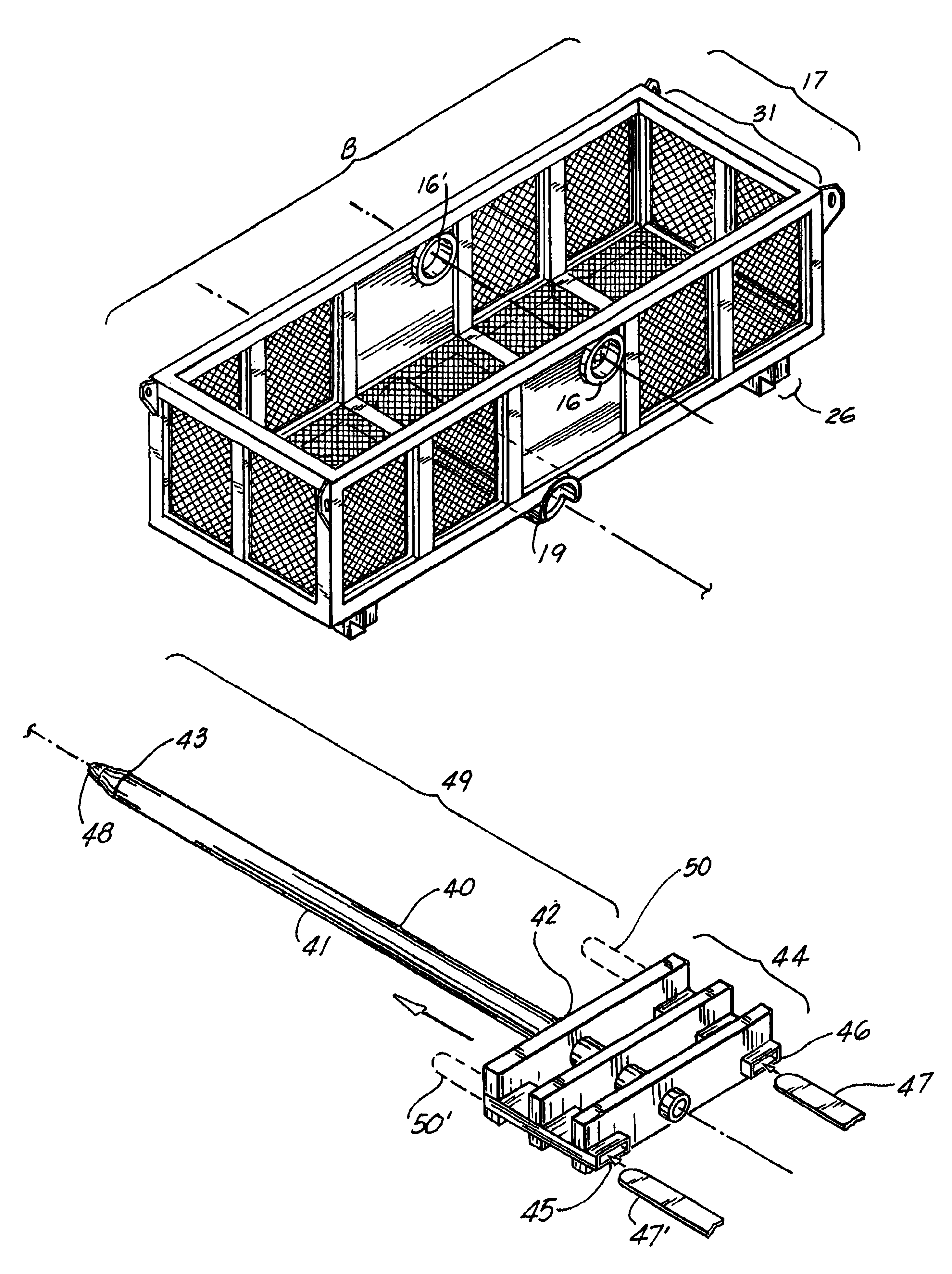
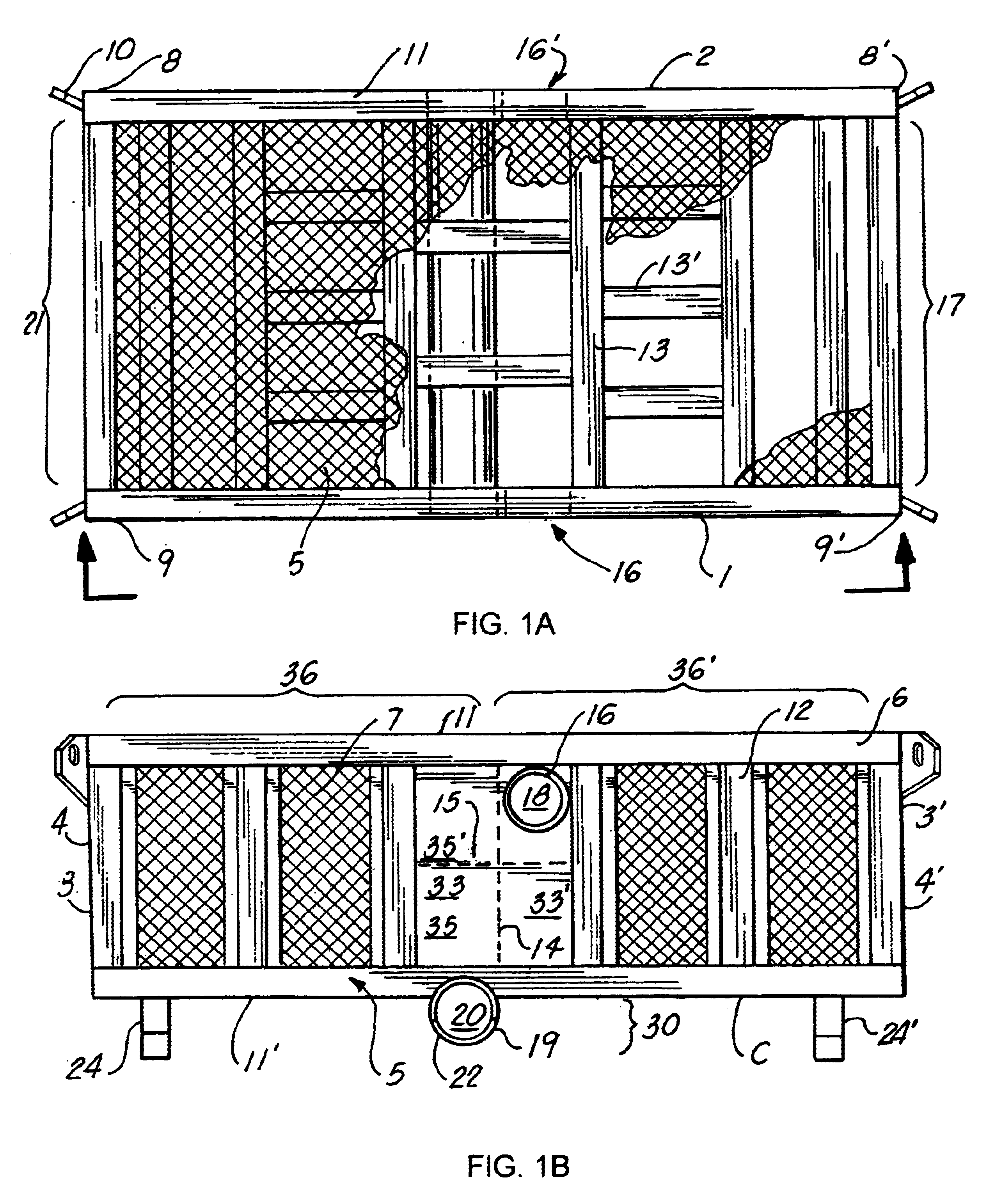
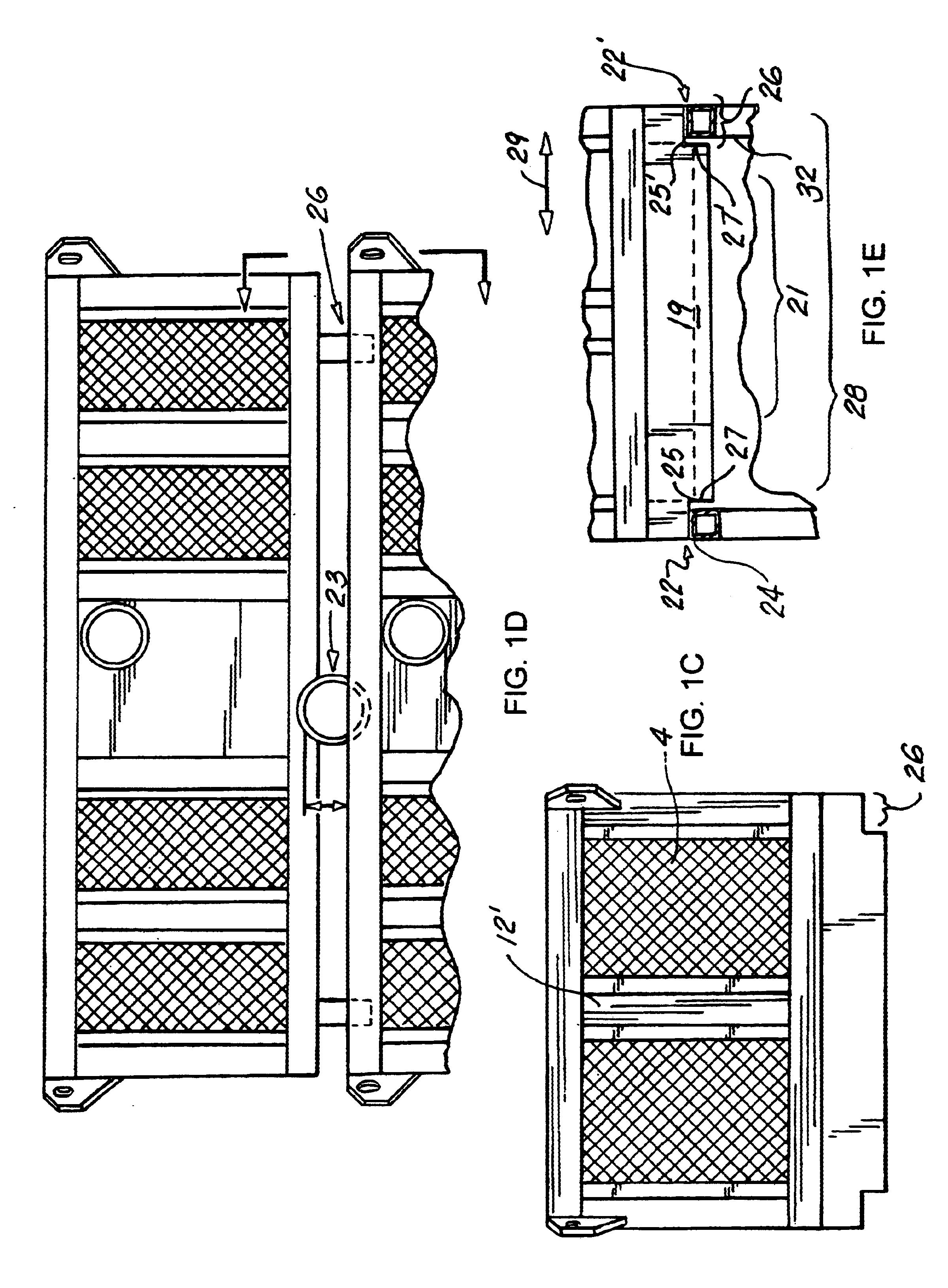
Referring to FIGS. 1A-1E, the cargo bin C of the present invention comprises first 1 and second 2 vertical walls having first 3 and second 3' ends joined by first 4 and second 4' end walls, respectively, forming first 8, second 8', third 9, and fourth 9' upper corners, which may have a lifting pad eye 10 emanating therefrom. A floor 5 is provided to join the lower portions of the four walls to form a bin holding area B.

A frame 6 of square tubing or the like forms the edges of the bin, including the top edge 11, bottom edge 11', vertical support members 12, and underlying horizontal stringer 13 and braces 13' forming the floor. A layer of heavy gauge expanded metal forms the walls 7 and floor 7' on the interior of the bin, reinforced by the frame.

Each pad eye 10 is configured to engage a lifting cable, with the cables ideally configured to form a lifting sling for the unit having a gross lifting capacity which would exceed the weight of any material filling the bin. Further, the heav...


PUM


Abstract

A cargo bin dumping system wherein there is provided a cargo bin as disclosed in the preferred embodiment of the present invention, with the addition of first and second lateral receiving stinger tubes for the engagement of a stinger therethrough, so as to facilitate the safe, and efficient dumping of the contents of a cargo basket into a waste bin or the like utilizing an ordinary forklift. A stinger specifically designed to work with the present system is also provided.

Description

The present invention relates to cargo storage systems, and in particular to a heavy-duty cargo bin unit configured for rugged use in hostile environments, such as in the oil drilling and production industry.The preferred embodiment of the present invention comprises a cargo bin unit of a generally rectilinear construction, fabricated of heavy gauge steel tubing, each cargo bin having a series of support members for spacing the basket above the floor, the members configured to facilitate lifting of the basket via a forklift or the like. Further, each of the support members is positioned to allow for the nested stacking of one cargo bin atop the other, such that the lower portion support members would fit snugly within the interior walls of the cargo bin upon which it is placed, thereby providing a locking of the stacked cargo bins to prevent tipping, while the upper portion of the support members rides upon the upper edges of the bin upon which it is stacked, so as to provide a spac...

Claims


Application Information

Patent Timeline
IPC IPC(8): B65D88/56B65D88/00B66F9/12B65D88/12
CPCB65D88/125B65D88/56B66F9/125
Inventor MOSER, ROBERTROOD, CHARLES H.
Owner MOSER ROBERT
Why Eureka
Try Eureka