Container, connection and production device

Active Publication Date: 2022-05-10
KOCHER PLASTIK MASCHBAUU
View PDF14 Cites 1 Cited by
  • Summary
  • Abstract
  • Description
  • Claims
  • Application Information

AI Technical Summary

Benefits of technology

[0019]A radially elastic design of the container opening in the sealing surface area is achieved in particular by reducing the mean wall thickness of the lead-in area and/or functional contact surface in comparison to the mean wall thickness of the other functional surfaces by approx. 20%-50%, preferably 20%-30% by including the adjacent outer wall parts of the individual functional surfaces. That is, there is an overall reduction in wall thickness in the actual so-to-say sealing line area while still providing sufficient axial stiffness to prevent buckling. For low actuation forces, a secure connection is then established for the withdrawal of the contents of a container between the withdrawal body and container.
[0020]In a particularly preferred embodiment of the container according to the invention, the functional contact surface forms an abutment cone which has an opening angle of 3.43 degrees (cone angle) or greater relative to the longitudinal axis of the container. The correspondingly determined opening angle of the lead-in area according to the invention is 30 degrees, respectively an oblique inclination of 15 degrees, that is half an opening angle. In particular, if the cone angle of the container in the area of its extraction point is greater than 3.43 degrees with respect to a cone angle of the withdrawal body, for instance in the form of a syringe, having a male cone part of 3.43 degrees or 6% in accordance with ISO 80369-7:2016 is selected, an interference-free connection process for the withdrawal body at low actuation forces and simultaneously very good fluid sealing is achieved. The opening angle of the additional conical lead-in area of 30 degrees is also a contributing factor. A value that on the one hand ensures a high line pressure between the functional contact surface and the withdrawal body. On the other hand, the valve forms an additional insertion aid in the sense of a conical extension for the free end face of the withdrawal body, to further facilitate the insertion process in the direction of the functional contact surface.
[0021]In a further preferred embodiment of the container according to the invention provision is made to equip it with further functional surfaces on the inside of the neck part to further bra

Problems solved by technology

This secure seal also results in low “joining forces” for the user.
The connection of syringes as a withdrawal device having filled drug containers, however, is particularly challenging.
If a container is to be produced in a cost-effective manner in large quantities and using other plastic materials (polypropylene, polyethylene) as described above, for instance as part of a blow molding process, including preferably the blow molding, filling and closing processes, the occurrence of leaks or leakages during the withdrawal operation from the container by the withdrawal device cannot always be definitely ruled out.
These leaks may be associated with an undesired risk to the patient.
The implementation of a reproducible sealing lip as a secure secondary seal, however, appears difficult, because the thin sealing lip is formed only by the user removing the ca

Method used


Image

  • Container, connection and production device
  • Container, connection and production device
  • Container, connection and production device

Examples


Embodiment Construction

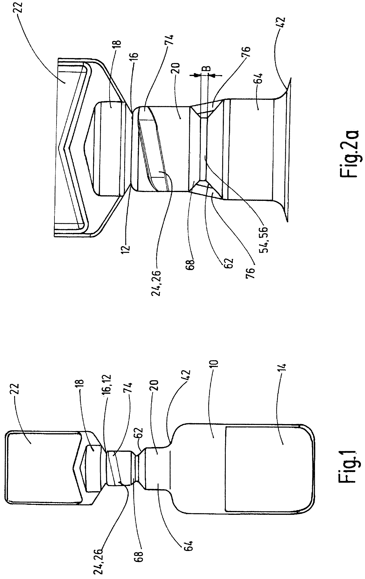
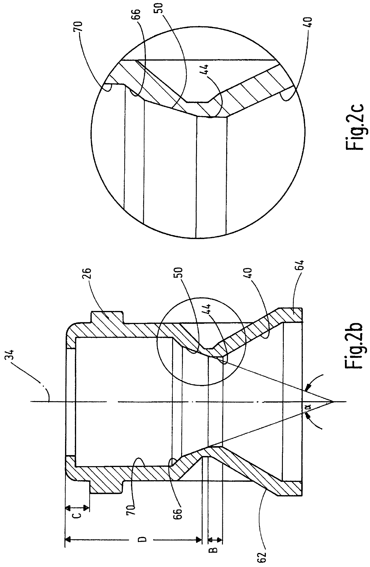
[0034]FIG. 1 shows an integral container as a whole prior to its opening in the form of an ampule of plastic material comprising a container part 10 for receiving liquid or semi-solid the contents 14 of the container 10 for medical purposes or the like that can be dispensed via a container opening 12. The container opening 12 is closed along a separation line 16 by a detachable head part 18. Head part 18 is adjoined by a neck part 20, which merges into the actual container part 10. The head part 18 has a handle 22, which can be used to twist off the head part 18 from the neck part 20 at the separation line 16, thereby opening the container opening 12 using low actuating torques / forces. FIG. 2b shows a cross-section of an exposed container opening 12 after the head part 18 has been twisted off by the handle 22, by way of example.

[0035]On the outer circumference, in the upper part of the neck part 20, a part of a threaded section 24 is shown in the manner of a female thread, which in ...


PUM


Abstract

A container, in particular an ampule, of a plastic material has a container part (10) for receiving the contents of a container (14) to be dispensed via a container opening (12). Opening (12) is closed by a head part (18) that can be separated along a separation line (16). The head part (18) is adjoined by a neck part (20), which has a plurality of different functional surfaces on the inner circumference. One functional contact surface (44) is used to seal against a withdrawal body (32), which is provided for withdrawing the contents of a container (14) when the container opening (12) is opened. A lead-in area (50) is provided as a further functional surface on the interior of the neck part (40) and differs geometrically from the functional contact surface (44). The lead-in area (50) seamlessly merges into the functional contact surface (44). The lead-in area (50) and the functional contact surface are located between the other functional surfaces in the neck part (20).

Description

FIELD OF THE INVENTION[0001]The invention relates to a container, in particular an ampule, formed of plastic material, having a container part for receiving the contents of the container to be dispensed via a container opening. The container opening is closed by a head part that can be separated along a separation line adjoined by a neck part. The neck part has a plurality of different functional surfaces on its inner circumference. One functional contact surface is used to seal against a withdrawal body, which is provided for withdrawing the contents of a container when the container opening is opened. In addition to the existing functional surfaces, a further functional surface is provided in the form of a lead-in area on the interior of the neck part for a safe withdrawal and a consistent and reliable production. The further functional surface geometrically differs in at least one characteristic from the characteristic of the one functional contact surface.BACKGROUND OF THE INVEN...

Claims


Application Information

Patent Timeline
IPC IPC(8): A61J1/06A61J1/14
CPCA61J1/067A61J1/1418A61J1/1431A61J1/1481B65D1/0238
Inventor GESER, JOHANNESSAUTER, ROLANDBOJBIC, DANIELSCHNEIDER, SVENGIEBELER, TORSTEN
Owner KOCHER PLASTIK MASCHBAUU
Why Eureka
Try Eureka