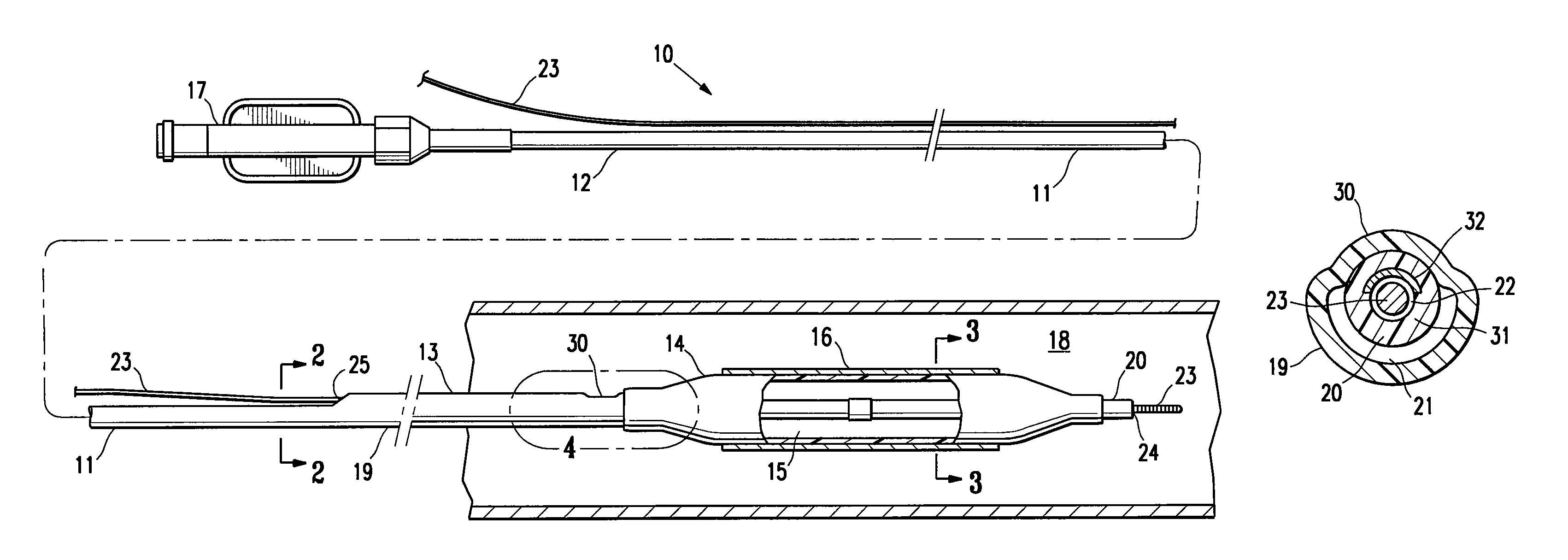
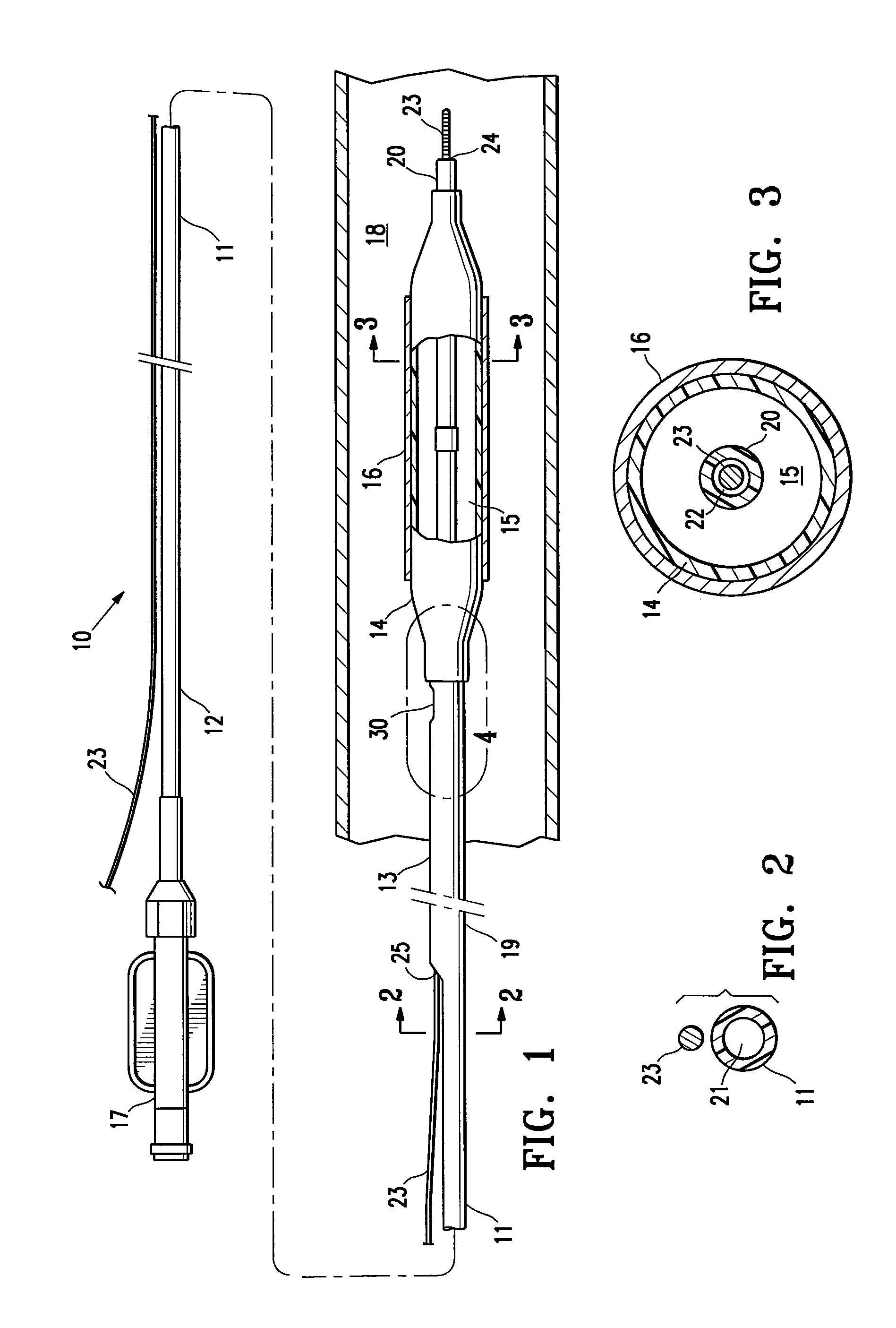
[0005]The invention is directed to a
balloon catheter having an elongated shaft and a balloon on a distal shaft section, the elongated shaft comprising an outer tubular member, and an inner tubular member with a bonded portion along which an outer surface of the inner tubular member is bonded to an inner surface of the outer tubular member. The inner tubular member has a
distal portion distal to the bonded portion with higher
axial compression stiffness and column strength than a proximal portion of the inner tubular member. The catheter has improved trackability, axial collapse resistance, pushability, and crossability, for improved ability to position the balloon at a desired location in a patient's body lumen.
[0007]The bonded portion of the inner tubular member links the inner tubular member to the outer tubular member, preferably at or adjacent to a stiffness transition in the inner tubular member. Specifically, a distal portion of the inner tubular member located distal to the bonded portion has a higher
axial compression stiffness and column strength than a proximal portion of the inner tubular member located proximal to the bonded portion. Additionally, in one embodiment, the proximal portion of the inner tubular member has a lower
bending stiffness than the distal portion of the inner tubular member. Preferably, the bonded portion is located at (i.e., radially aligned with) or longitudinally adjacent to the proximal end of the balloon. In a presently preferred embodiment, the bonded portion has a distal end located proximal to the balloon and typically a relatively
short distance from the proximal end of the balloon and a relatively long distance from the proximal end of the inner tubular member. As a result, the length of the distal portion of the inner tubular member extending distally from the bonded portion, through the balloon interior to the distal end of the inner tubular member, is minimized relative to the length of the proximal portion of the inner tubular member. The configuration provides a maximum length to the highly flexible proximal portion of the inner tubular member. In one embodiment, the distal portion of the inner tubular member has a length equal to about 1 to about 5% of the length of the entire shaft. By linking a portion of the inner tubular member to the outer tubular member near the proximal end of the balloon, the axial compression stiffness of the proximal portion of the inner tubular member has little or no influence on the amount of
axial load that is carried by the balloon. Consequently, in the catheter of the invention, the inner tubular member proximal portion has a low
bending stiffness and a concurrently low axial stiffness, with the outer tubular member carrying a substantial portion of the total
axial force along the shaft up to the adjoining balloon. Distal to the outer tubular member, the distal portion of the inner tubular member is provided with sufficient column stiffness and strength to prevent or inhibit it from elastically shortening or telescopically collapsing under
axial load. As a result, the catheter shaft is highly flexible, and nonetheless transfers the majority of applied axial load to the distal end of the balloon and thereby prevents or inhibits buckling of the balloon during advancement of the catheter in the patient's body lumen.
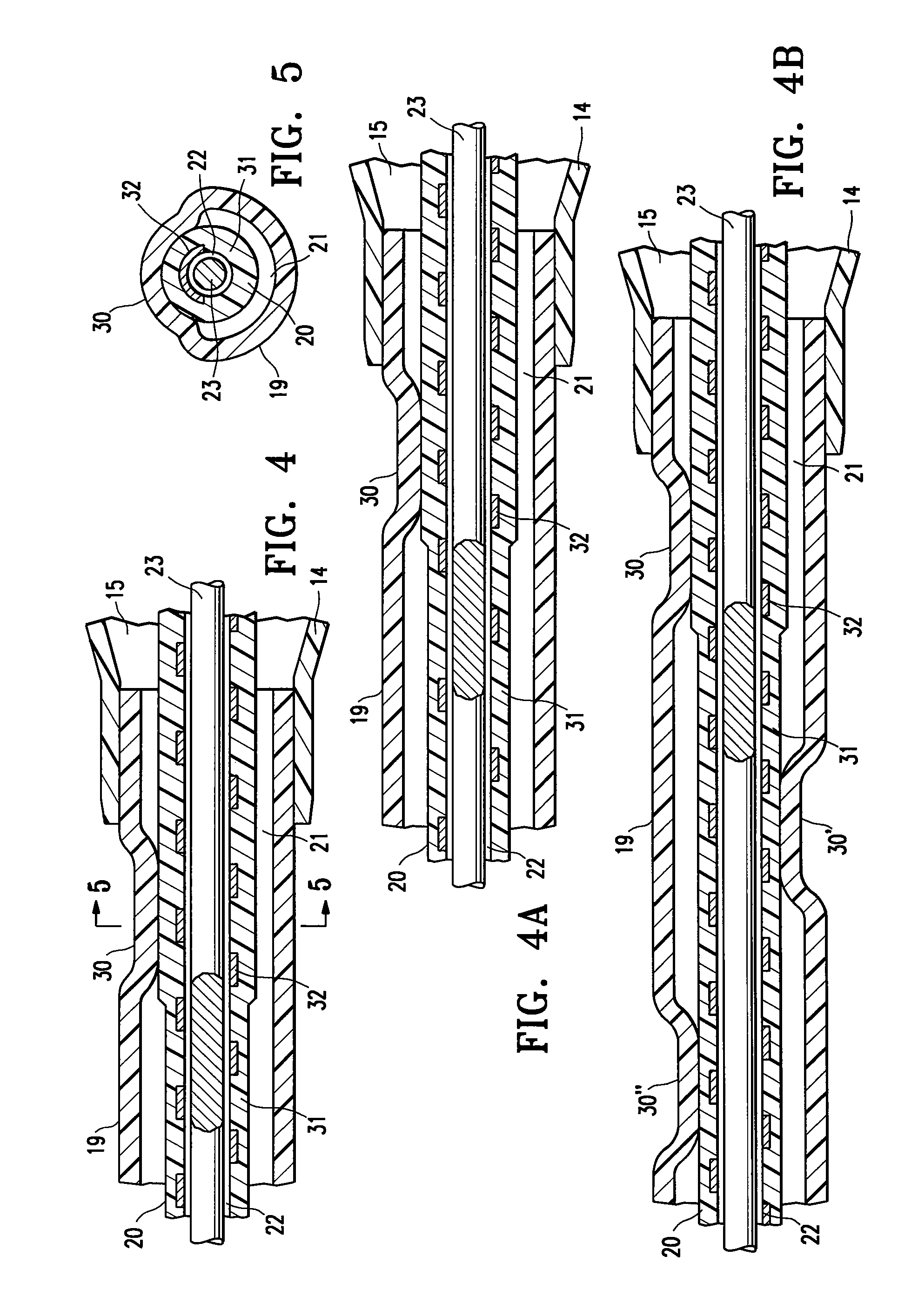
[0011]In a presently preferred embodiment, the inner tubular member comprises a polymeric tube with a coiled reinforcing member embedded therein. Although the distal portion of the inner tubular member typically has a higher axial compression stiffness and column strength than the proximal portion thereof, the coiled reinforcing member allows the inner tubular member to have a relatively low bending stiffness and high radial collapse resistance throughout, for excellent catheter trackability and guidewire movement even after inflation of the balloon at relatively high inflation pressures. The coiled reinforcing member preferably extends at least in part within the proximal and distal portions of the inner tubular member, and in one embodiment, the coiled reinforcing member extends along the entire length of the inner tubular member. In one embodiment, the coiled reinforcing member has a uniform
pitch, stiffness, and / or column strength throughout its length. Alternatively, the coiled reinforcing member extending along the distal portion of the inner tubular member has a tighter coil
pitch (i.e., more closely spaced coils) than along the proximal portion of the inner tubular member, or otherwise provided with a higher axial stiffness and column strength along the distal portion, to produce the stiffer distal portion of the inner tubular member. For example, a longitudinally extending wire member bonded to the distal portion of the coiled reinforcing member selectively stiffens the distal portion of the inner tubular member. In one embodiment, two types or plies of wire or ribbon form the reinforcing member, with the first type reinforcing the entire length of the inner tubular member and the second type located in the distal portion of the inner tubular member to selectively stiffen the distal portion of the inner tubular member by, for example, preventing the distal coils from moving closer together or bunching under axial load. Similarly, a braided reinforcing member having a variable pick count (number of
braid crossover points per unit of
axial length) imparting a stiffness transition may alternatively be used to form the inner tubular member. The resulting catheter shaft, formed by the inner and outer tubular members, has an improved low bending stiffness throughout the length of the inner member, for improved trackability.
[0013]The inner tubular member having a stiffness transition can be formed using a variety of suitable methods. For example, in one embodiment, forming the inner tubular member comprises
necking a proximal part of a polymeric tube to reduce a wall thickness and an outer
diameter thereof without reducing an inner
diameter thereof, to thereby reduce the axial compression stiffness of the proximal part of the polymeric tube, and embedding a coiled reinforcing member in the polymeric tube. In another embodiment, forming the inner tubular member comprises increasing the wall thickness of a distal section of a polymeric tubular member having a coiled reinforcing member embedded therein, by a method selected from the group consisting of heat shrinking an outer polymeric layer onto the distal section of the coil reinforced polymeric tubular member, melt bonding an outer polymeric layer onto the distal section of the coil reinforced polymeric tubular member, or
dip coating the distal section of the coiled reinforced polymeric tubular member. In another embodiment, forming the inner tubular member comprises joining the distal end of a first tube to a proximal end of a second tube to form a polymeric tubular member, and fusing the polymeric tubular member to a coiled reinforcing member, and the second tube is formed of a polymeric material having a higher
Shore durometer
hardness or has a wall thickness greater than a wall thickness of the first tube. In another embodiment, forming the inner tubular member comprises fusing a polymeric tube to a braided reinforcing member, the braided reinforcing member having a distal part with a pick count which is higher than a pick count of a proximal part of the braided reinforcing member. In another embodiment, forming the inner tubular member comprises applying an
adhesive or melt bondable
polymer to a portion of a mandrel, and applying a coil on the mandrel with a distal part of the coil on the
adhesive or melt bondable
polymer, and fusing a polymeric layer on the coil, to form the coil reinforced polymeric tubular member. In another embodiment, forming the inner tubular member comprises joining the distal end of a coil reinforced polymeric tubular member to the proximal end of a
polymer tube having a greater axial stiffness and column strength than the coil reinforced polymeric tubular member. In another embodiment, forming the inner tubular member comprises irradiating or heat stabilizing a distal part of a polymeric tube to increase the stiffness of the distal part of the polymeric tube.
[0014]The
balloon catheter of the invention has improved pushability and trackability, due to the low bending stiffness inner tubular member having a bonded portion bonded to the outer tubular member and excellent force transmission through the balloon interior to the distal tip. The shaft configuration prevents or inhibits the balloon from buckling or bunching during advancement in the patient's
blood vessel, despite the low bending stiffness of the inner tubular member and resulting excellent trackability. Thus, the catheter shaft of the invention accommodates typically competing considerations in the design of catheters, to facilitate positioning the balloon at a desired location in the patient's
blood vessel. These and other advantages of the invention will become more apparent from the following detailed description of the invention and the accompanying exemplary drawings.

