Heart valve and method for insertion of the heart valve into a bodily vessel

a heart valve and stent technology, applied in the field of heart valves, can solve the problems that the heart valve with a stent may not function exactly like the native valve, and achieve the effects of reducing the thickness of the wall, and facilitating separation of the sheath

Inactive Publication Date: 2006-09-28
RUIZ CARLOS +1
View PDF14 Cites 60 Cited by
  • Summary
  • Abstract
  • Description
  • Claims
  • Application Information

AI Technical Summary

Benefits of technology

[0036] The insertion sheath may also be configured to split, for example, circumferentially, into proximal and distal portions at a predetermined location on the insertion sheath upon application of a pulling force on opposite ends of the sheath or upon twisting of the proximal and distal portions relative to each other. The sheath may be weakened at the predetermined location relative to other locations along the sheath so as to facilitate separation of the sheath into two parts and to assure that separation of the sheath occurs at the predetermined location. For example, the sheath may have a reduced wall thickness or may be partially cut at the predetermined location so as to facilitate separation of the sheath into two parts and to assure that the separation occurs at the predetermined location.

Problems solved by technology

However, this is only one of many functions that is performed physiologically and functionally, although not readily apparent by the novice, by the native valve.
Thus, a valve with a stent may not function exactly like the native valve.

Method used


Image

  • Heart valve and method for insertion of the heart valve into a bodily vessel
  • Heart valve and method for insertion of the heart valve into a bodily vessel
  • Heart valve and method for insertion of the heart valve into a bodily vessel

Examples


Embodiment Construction

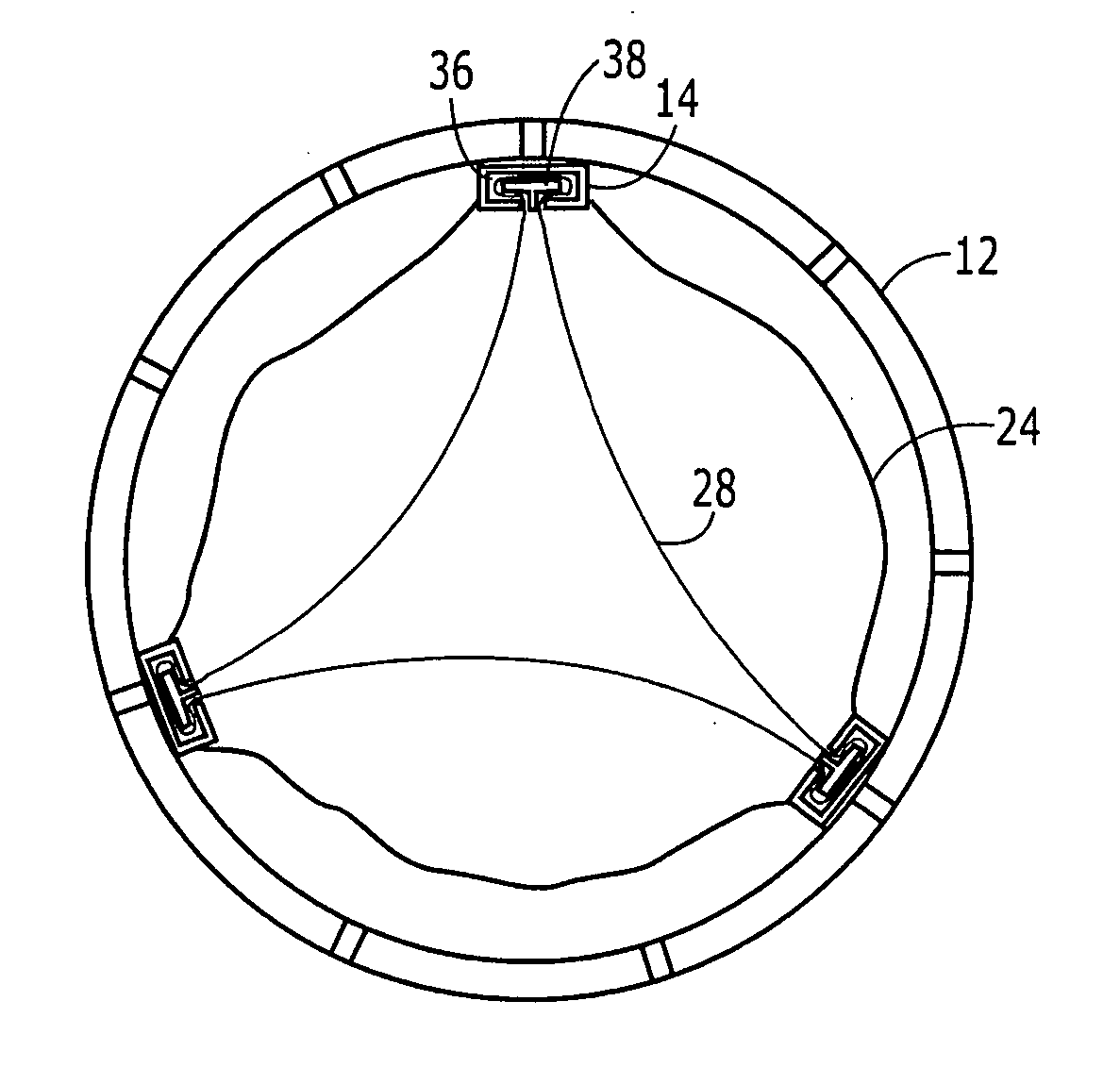
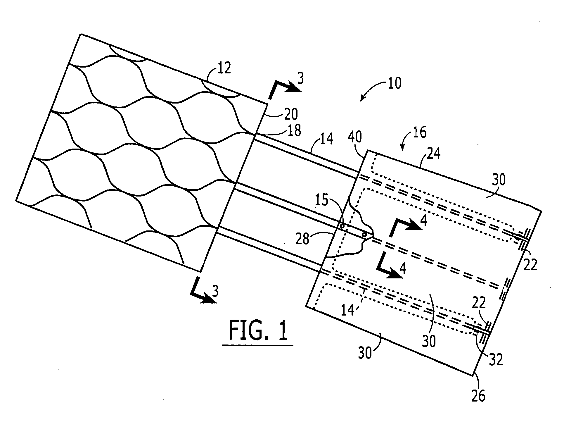
[0065]FIG. 1 illustrates a valve 10 of an exemplary embodiment of the present invention including an anchor portion 12, connectors 14 and a valve portion 16 spaced a distance away from anchor portion 12. Connectors 14 are connected on a distal end 18 to a proximal end 20 of anchor portion 12. Connectors 14 may extend at least partially along the length of the anchor portion 12. Connectors 14 may be connected to anchor portion 12, for example, by welding, suturing, gluing, clipping, rivets, etc. Connectors 14 may also be integral with anchor portion 12.

[0066] Connectors 14 extend along the commissural lines of the valve portion 16 a sufficient length so as to assure a strong connection with the valve portion 16. The connectors 14 may also be connected to the valve portion 16 at different points along its circumference. The valve portion 16 may be covered by a cloth 24 made from, for example, DACRON®, but also may be used without such covering. The portion of the connectors 14 connec...


PUM


Abstract

A heart valve includes a stent for fixing the heart valve in a bodily vessel and a stentless valve portion for restricting the flow of blood through the valve to a single direction. The valve portion is supported and suspended in the bodily vessel via connectors spanning a gap between the valve portion and the stent or by a direct end-to-end connection with the anchor portion.

Description

INCORPORATION BY REFERENCE [0001] U.S. Provisional Patent Application No. 60 / 593,173, filed on Dec. 16, 2004 and entitled “Prosthetic Valve,” is expressly incorporated herein in its entirety by reference thereto. U.S. patent application Ser. No. ______ , entitled “A Separable Sheath and Method for Insertion of a Medical Device into a Bodily Vessel Using a Separable Sheath,” bearing Attorney Docket No. 13430 / 3, filed in the United States Patent and Trademark Office on the even date herewith, is also expressly incorporated herein in its entirety by reference thereto.FIELD OF THE INVENTION [0002] The present invention relates to a heart valve and a method for its insertion into a bodily vessel. BACKGROUND INFORMATION [0003] Valves, mechanical or biological, such as heart valves, can be implanted into a bodily vessel, for example, to replace native valves exhibiting abnormal anatomy and / or function as a result of congenital or acquired disease. Available prosthesis include two categorie...

Claims


Application Information

Patent Timeline
Patent Type & Authority Applications(United States)
IPC IPC(8): A61F2/24
CPCA61F2/2412A61F2/2418A61F2/2433A61F2220/0066A61F2/97A61F2220/0041A61F2220/005A61F2/2436
Inventor RUIZ, CARLOSDORROS, GERALD
Owner RUIZ CARLOS
Why Eureka
Try Eureka