Front load pressure jacket system with syringe holder and light illumination

a pressure jacket and syringe technology, applied in the field of pressure jacket systems, can solve the problems of patient tubing typically having to be disconnected from the syringe, bursting or leakage of pressurized fluid around the seal, and potentially unsafe or hazardous conditions

Active Publication Date: 2009-06-23
BAYER HEALTHCARE LLC
View PDF38 Cites 60 Cited by
  • Summary
  • Abstract
  • Description
  • Claims
  • Application Information

AI Technical Summary

Benefits of technology

[0041]The pressure jacket has a distal end defining a syringe receiving opening for receiving the syringe. The distal end of the pressure jacket may define a beveled portion forming an acute angle with a central axis of the pressure jacket. With the at least one support arm in the first position, the syringe retaining member may be pivotal between a syringe retaining position wherein a syringe facing side of the...

Problems solved by technology

A pressure jacket serves to limit radial expansion of a syringe, which may lead to bursting or to leaks of the pressurized fluid around the seal(s) of the syringe plunger.
A disadvantage of rear loading pressure jacketed injectors is that, after an injection, the patient tubing typically must be disconnected from the syringe before the syringe may be extracted from the rear of the pressure jacket and discarde...

Method used


Image

  • Front load pressure jacket system with syringe holder and light illumination
  • Front load pressure jacket system with syringe holder and light illumination
  • Front load pressure jacket system with syringe holder and light illumination

Examples


Embodiment Construction

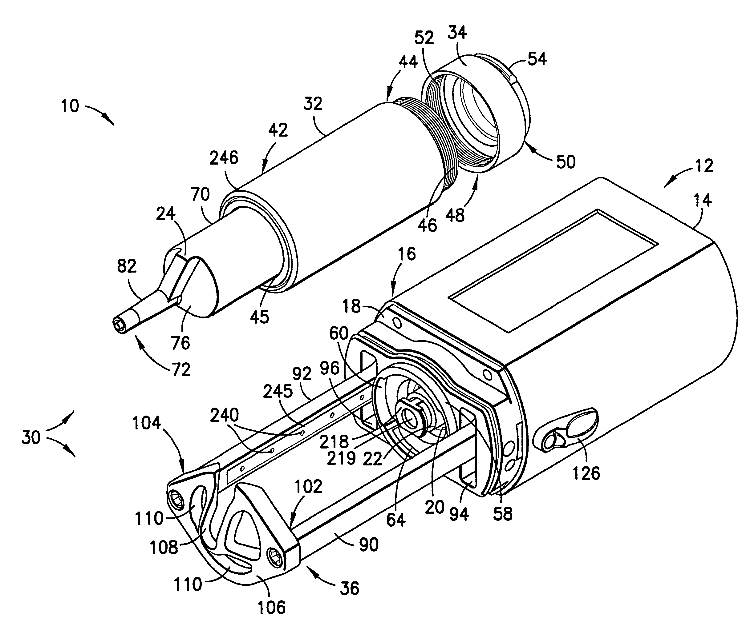
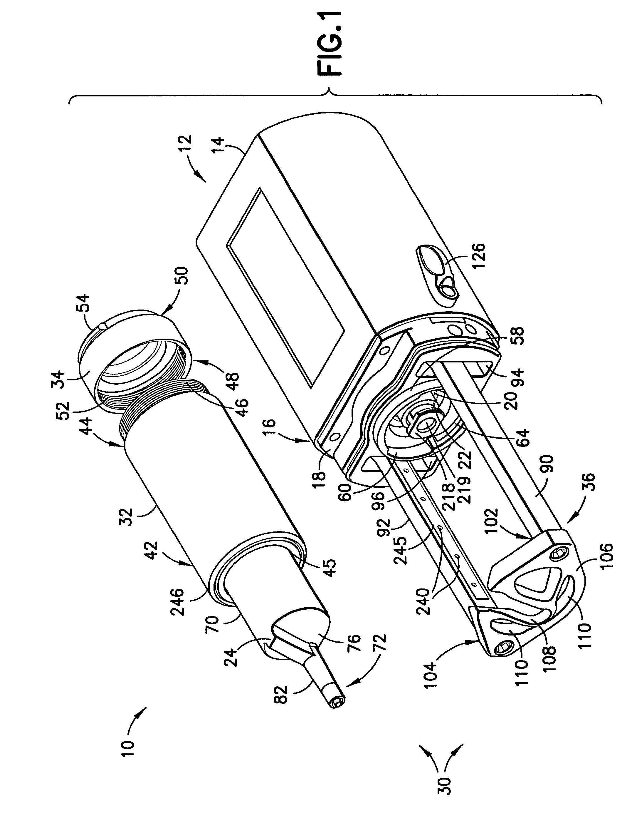
[0075]FIG. 1 shows a fluid injection apparatus 10 in accordance with the present invention. The fluid injection apparatus 10 includes an injector head 12, which may be supported on a support structure (not shown). The injector head 12 includes an injector housing 14 having a front end 16. A faceplate 18 is attached to the front end 16 of the injector housing 14 and encloses the front end 16 of the injector housing 14. The faceplate 18 may be secured to the front end 16 of the injector housing 14 by conventional means (i.e., mechanical fasteners and the like) or be integrally formed with the injector housing 14.

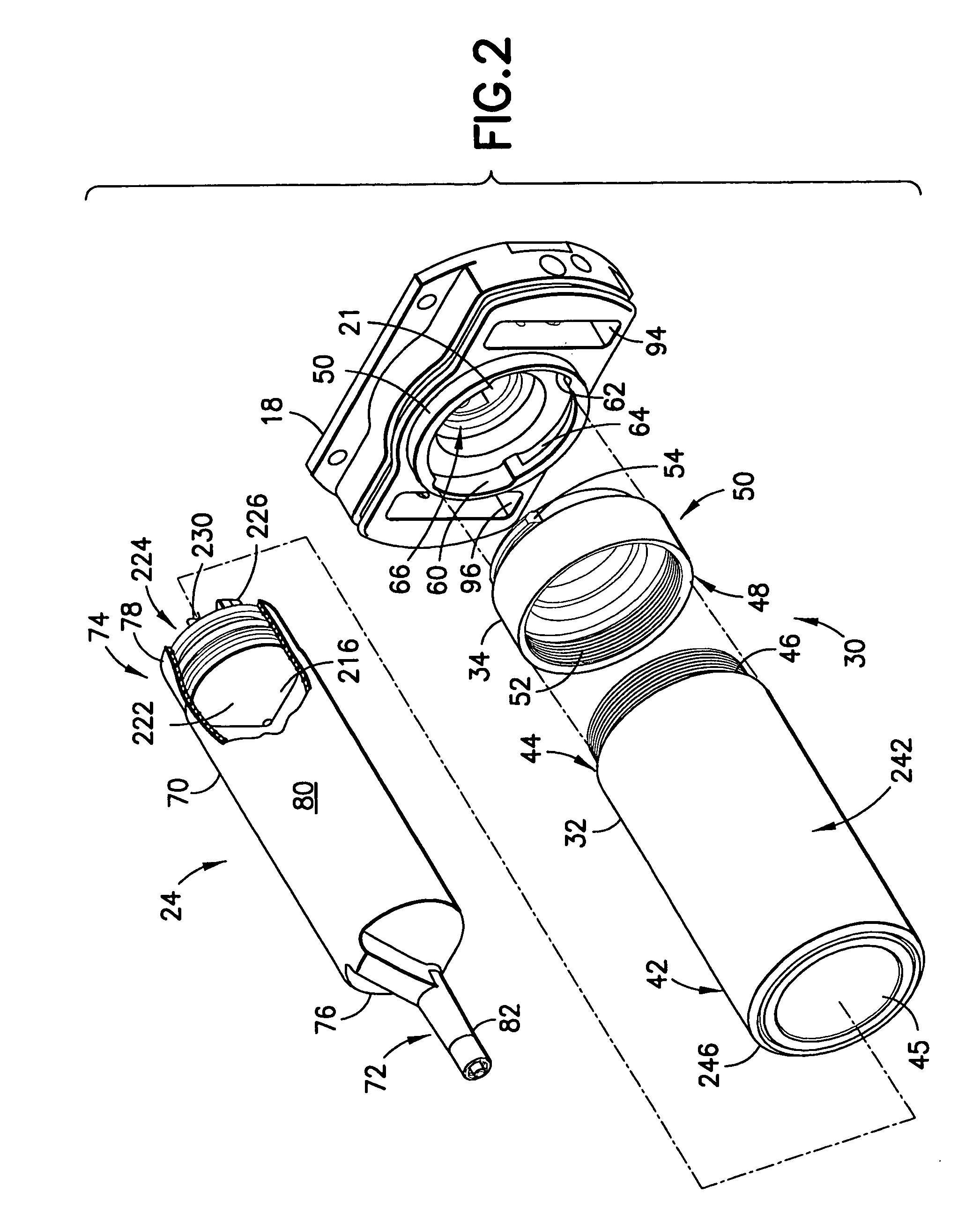
[0076]Referring to FIGS. 1-4, the injector housing 14 has a central opening 20 aligned with a central passage 21 defined by the faceplate 18 and through which an injector drive piston 22 of the injector head 12 is extendable and retractable. The details of the injector head 12 and, more particularly, the injector drive piston 22 are described in U.S. Pat. No. 5,383,858, which ...


PUM


Abstract

The fluid injection apparatus for use with a syringe includes an injector and a pressure jacket assembly associated with the injector. The injector includes a housing defining a central opening and a drive piston extendable through the central opening for imparting motive forces to a syringe plunger disposed within the syringe. The pressure jacket assembly includes a pressure jacket and at least one support arm associated with and extending outward from the housing. A syringe retaining member is attached to the at least one support arm. The syringe-retaining member defines a syringe receiving slot for receiving at least a portion of the syringe. A light source is located on the support arm and faces the pressure jacket for illuminating the syringe. The syringe includes an alignment flange defining a bulged air bubble viewing window (see A). The alignment flange is used to properly orient the syringe in the pressure jacket.

Description

BACKGROUND OF THE INVENTION[0001]1. Technical Field of the Invention[0002]This invention relates generally to pressure jacket systems for securing a syringe to an injector, to syringes for use with pressure jackets systems, and to methods of loading syringes in and removing syringes from pressure jacket systems. More specifically, the invention relates to front-loading pressure jacket systems and methods for allowing front loading and removal of syringes therefrom, and to syringes of special construction for use with, for example, pressure jackets.[0003]2. Description of Related Art[0004]In the medical field, patients are often injected with fluids in procedures such as angiography, computed tomography (CT), and magnetic resonance imaging (MRI). In such procedures, which require controlled injection of relatively large volumes of fluid into a patient, a catheter is used as a conduit for the fluid, which is connected to the syringe(s) by a connector tube. The syringe(s) is mounted on...

Claims


Application Information

Patent Timeline
IPC IPC(8): A61M37/00A61M5/145
CPCA61M5/14546A61M5/14566A61M2205/587A61M2005/2437
Inventor SCHRIVER, RALPH H.SPOHN, MICHAEL A.JOYCE, THOMAS P.CRITCHLOW, RICHARD G.GRUBIC, HERBERT M.JONGEWAARD, MARK PAUL
Owner BAYER HEALTHCARE LLC
Why Eureka
Try Eureka