Flexible Tissue Removal Devices and Methods

a tissue removal and flexible technology, applied in the field of medical/surgical devices and methods, can solve the problems of difficult to modify certain tissues to achieve a desired effect, more technically challenging procedures, and reduced or even no direct visualization, and achieve the effect of inhibiting damage to neural tissu

a tissue removal and flexible technology, applied in the field of medical/surgical devices and methods, can solve the problems of difficult to modify certain tissues to achieve a desired effect, more technically challenging procedures, and reduced or even no direct visualization, and achieve the effect of inhibiting damage to neural tissu

US20070225703A1Active Publication Date: 2007-09-27MIS IP HLDG LLC +1

Image

  • Flexible Tissue Removal Devices and Methods
  • Flexible Tissue Removal Devices and Methods
  • Flexible Tissue Removal Devices and Methods

Examples


Embodiment Construction

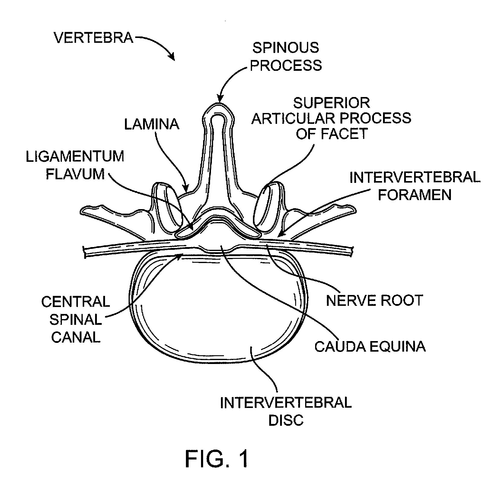
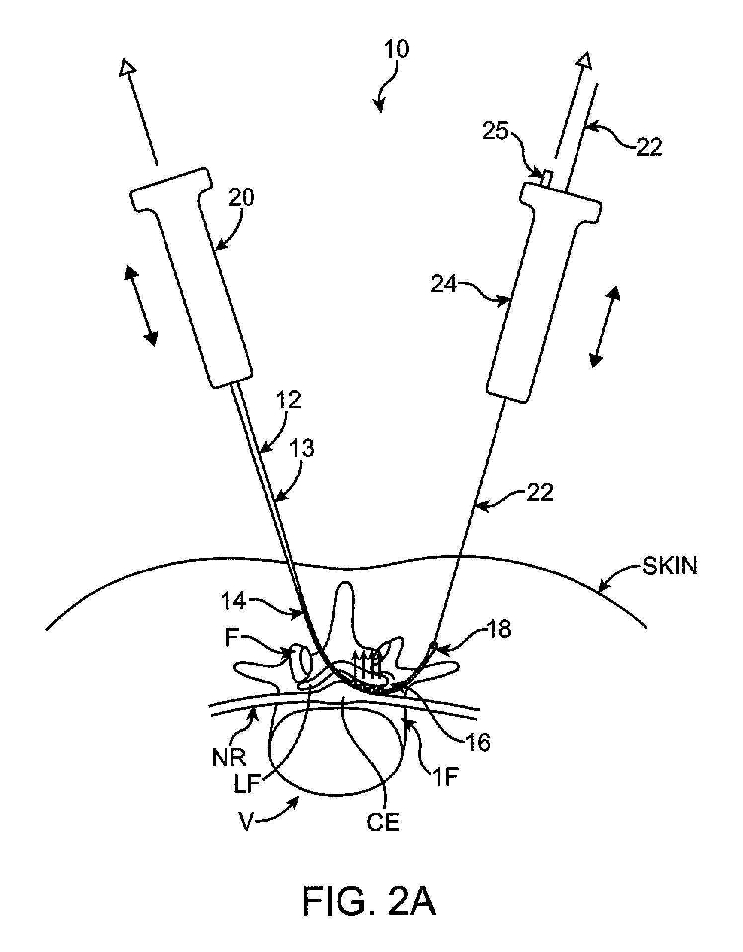
[0070] Various embodiments of tissue modification devices and systems, as well as methods for making and using same, are provided. Although much of the following description and accompanying drawing figures generally focuses on surgical procedures in spine, in alternative embodiments, devices, systems and methods of the present invention may be used in any of a number of other anatomical locations in a patient's body. For example, in some embodiments, flexible tissue modification devices of the present invention may be used in minimally invasive procedures in the shoulder, elbow, wrist, hand, hip, knee, foot, ankle, other joints, or other anatomical locations in the body. Similarly, although some embodiments may be used to remove or otherwise modify ligamentum flavum and / or bone in a spine to treat spinal stenosis, in alternative embodiments, any of a number of other tissues may be modified to treat any of a number of other conditions. For example, in various embodiments, treated ti...


PUM


Abstract

A device for modifying tissue in a patient may include: an elongate body having a rigid proximal portion and a flexible distal portion having first and second major surfaces; a proximal handle coupled with the proximal portion of the body; one or more tissue modifying members disposed along the first major surface of the distal portion of the body; a guidewire coupled with and extending from the distal portion of the body; and a distal handle removably couplable with the guidewire outside the patient.

Description

CROSS-REFERENCES TO RELATED APPLICATIONS [0001] The present application is a continuation-in-part of U.S. patent application Ser. No. 11 / 429,377 (Attorney Docket No. 026445-000723US), filed May 4, 2006, entitled “Flexible Tissue Rasp,” and also claims the benefit under 35 USC 119(e) of U.S. Provisional Patent Application No. 60 / 869,070 (Attorney Docket No. 026445-000725US), filed Dec. 7, 2006, entitled “Flexible Tissue Removal Devices and Methods,” both of which are hereby incorporated fully by reference. The present application is related to, but does not claim priority from, PCT Patent Application Pub. No. PCT / US2005 / 037136, titled “Devices and Methods for Selective Surgical Removal of Tissue, filed Oct. 15, 2005, which is hereby incorporated fully by reference.BACKGROUND OF THE INVENTION [0002] The present invention relates generally to medical / surgical devices and methods. More specifically, the present invention relates to flexible tissue modification devices and methods. [0003...

Claims


Application Information

Patent Timeline
27 Sep 2007
Publication
US20070225703A1
IPC
A61F5/00
CPC
A61B17/00234; A61B2017/143; A61B17/14; A61B17/1659; A61B17/1671; A61B17/1757; A61B17/32; A61B17/320016
Inventors
SCHMITZ, GREGORY P.; BLEICH, JEFFREY L.