Wear assembly for the digging edge of an excavator

Active Publication Date: 2006-01-17
ESCO GRP LLC
View PDF83 Cites 116 Cited by
  • Summary
  • Abstract
  • Description
  • Claims
  • Application Information

AI Technical Summary

Benefits of technology

[0012]In one construction, the bosses are formed to be generally L-shaped with a stem that fits into the rear end of the through-hole in the lip, and a main body that lies along a face of the lip to cooperate with the wear member. Bosses are preferably provided along the inner face and the outer face of the lip to hold the inner and outer legs of the wear members. The interconnection of the legs and bosses resists shifting of the legs which in the past has led to the stressing, bending and loosening of the locks. Preferably, the bosses are welded to the lip and to each other in the through-holes. In this way, a lip formed to accommodate a Whisler-style adapter can be easily modified to make use of the present invention.
[0013]In one preferred embodiment, a threaded wedge and spool assembly is used to secure the wear member in place on the lip. Specifically, a conically shaped wedge includes a thread structure that engages a cooperating thread structure on the spool so that the wedge is driven into and out of the through-hole via rotation of the wedge. The use of a threaded wedge and spool eases installation and removal of the lock, and reduces the risk of lock loss during use of the excavator. Moreover, the threaded wedge can be easily retightened to keep the wear member snugly mounted on the lip.
[0014]In another aspect of the invention, an insert is provided at t

Problems solved by technology

As can be appreciated, the wear members, and particularly the teeth, are often placed in harsh working conditions where they are subjected to very heavy loading and a high degree of wearing.
Although the points wear out most frequently, the adapters are also subjected to wear and require periodic replacement.
Although welding securely attaches the adapter to the bucket to withstand the heavy loads, the replacement of weld-on adapters is difficult and typically performed at a shop rather than in the field.
This causes the bucket to be placed out of commission, which, particularly in the case of the larger buckets, can result in a serious economic loss for the operator of a mine or other e

Method used


Image

  • Wear assembly for the digging edge of an excavator
  • Wear assembly for the digging edge of an excavator
  • Wear assembly for the digging edge of an excavator

Examples


Example

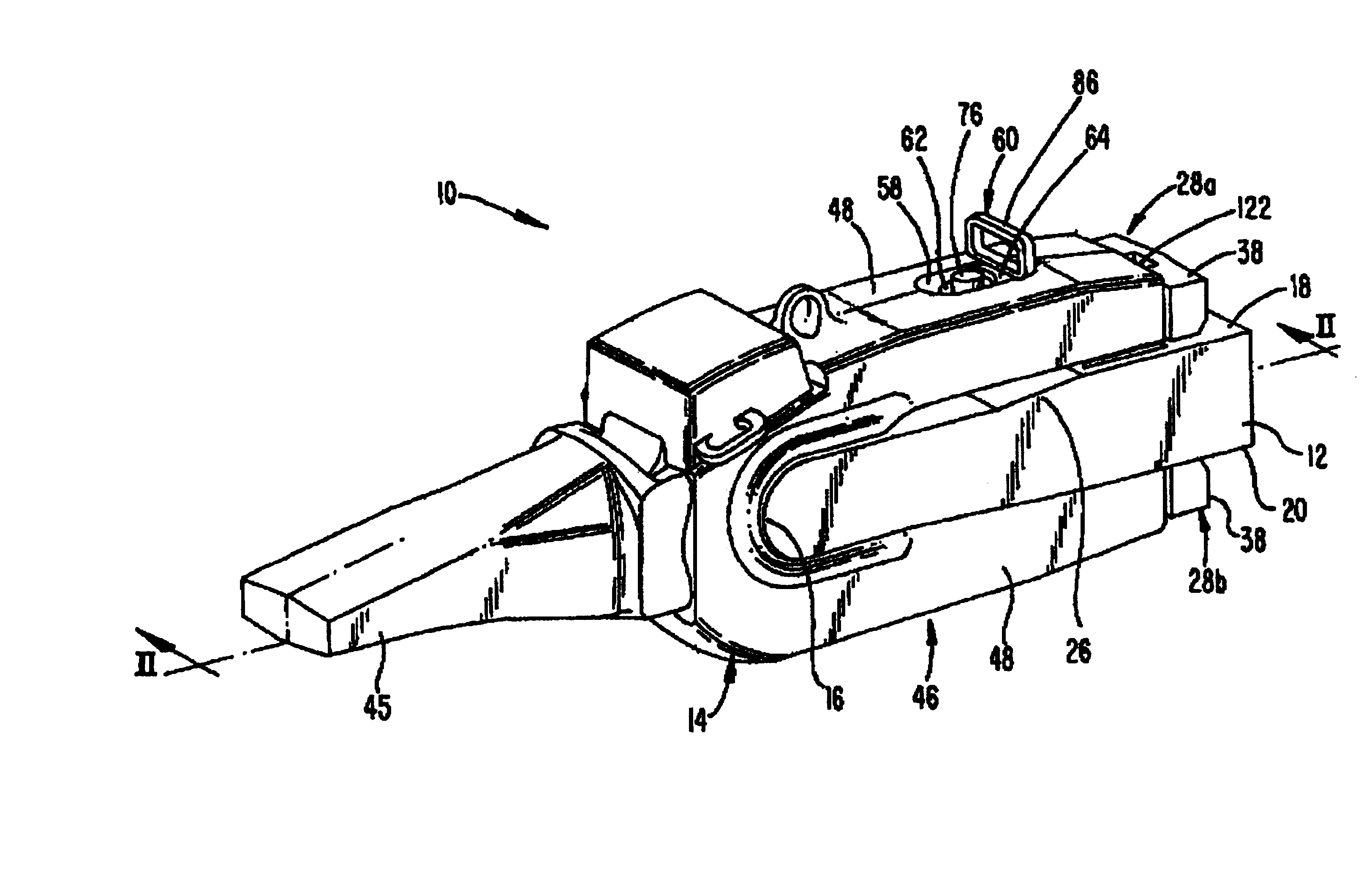
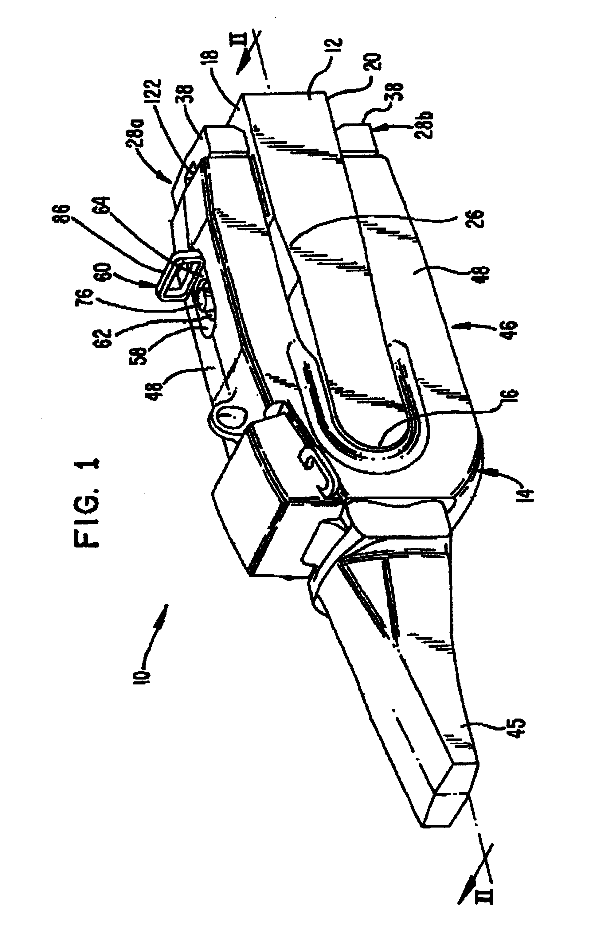
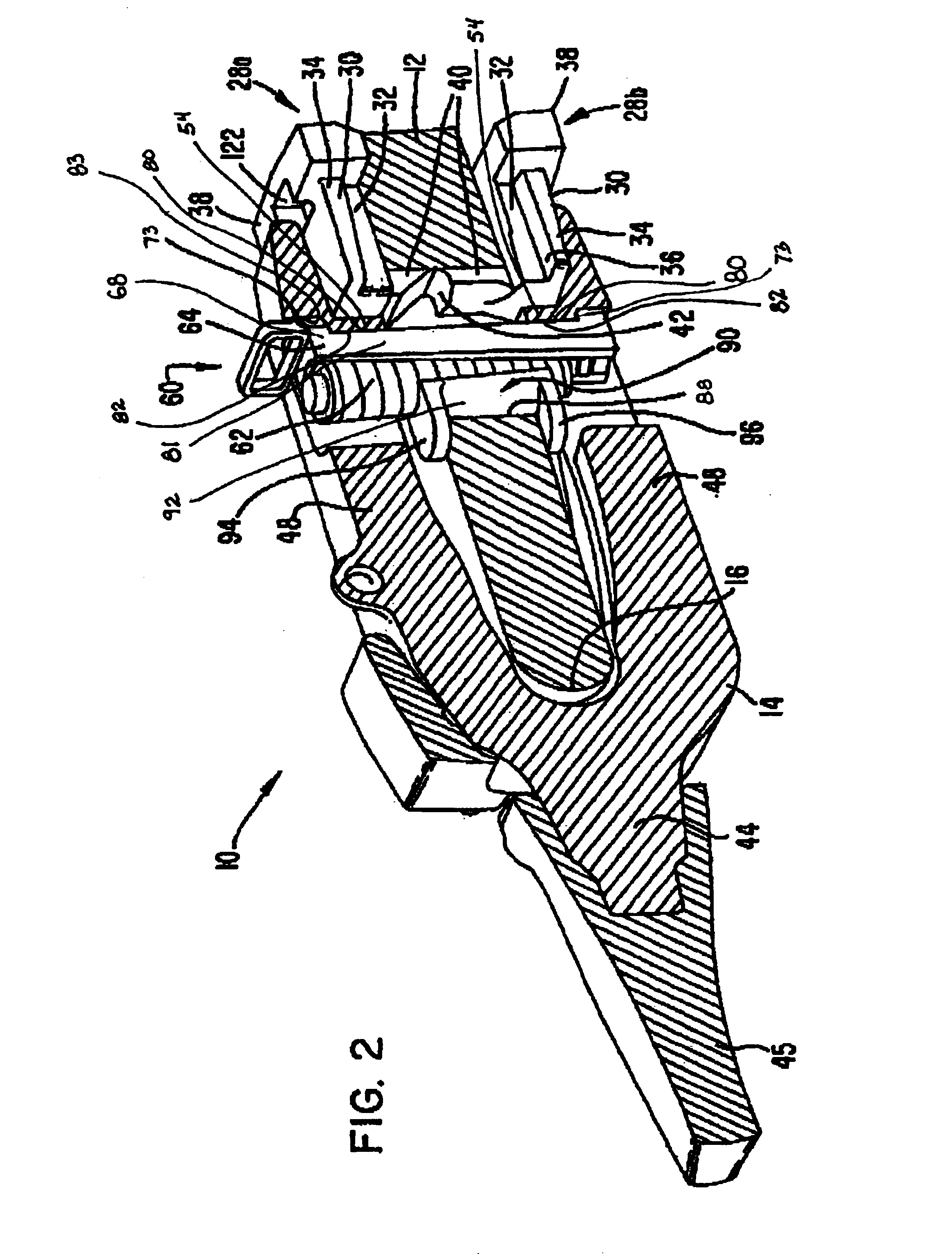
[0036]The present invention relates to a wear assembly 10 for mounting a wear member to a bucket or other excavator (FIG. 1). The present invention is particularly suited for mounting an adapter 14 for an excavating tooth to a lip, but could also be used to secure other wear members, such as shrouds. For ease of discussion, the invention will be described in terms of mounting an adapter to a lip of a bucket.

[0037]In one example, lip 12 defines a digging edge 16 of a bucket, and includes an inner face 18 and an outer face 20 (FIGS. 1-3 and 9). A front tab 22 preferably projects forward from the digging edge to aid in placing and supporting the adapter 14. A through-hole or keyway 24 is provided in the lip directly rearward of tab 22. While only a small portion of the lip is shown in the drawings, the lip would ordinarily include a series of spaced apart tabs and through-holes for the mounting of several teeth to the bucket. In the illustrated embodiment, the lip has a rounded digging...


PUM


Abstract

A wear assembly for attaching wear members to a lip of an excavator includes a wear member, a boss and a lock. The lip includes an inner face, an outer face, a digging edge and a series of through-holes spaced rearward of the digging edge. The bosses are each fixed to a face of the lip at a position rearward of the through-holes. The wear members each include slots to receive the boss adjacent their rear ends, and openings for receiving the locks at a position forward of the bosses. The openings are aligned with the through-holes in the lip. The lock includes a wedge and spool arrangement.

Description

FIELD OF THE INVENTION[0001]The present invention pertains to a wear assembly and particularly for the attachment of a wear member to the digging edge of a bucket or other excavator.BACKGROUND OF THE INVENTION[0002]It is a common practice to secure wear members in the form of teeth and shrouds along the digging edge of a bucket or other excavator to protect the front lip from premature wear. The teeth project forward of the lip to ease penetration and break up the ground to be gathered in the bucket. The shrouds are mounted to the lip between the teeth. As can be appreciated, the wear members, and particularly the teeth, are often placed in harsh working conditions where they are subjected to very heavy loading and a high degree of wearing.[0003]Excavating teeth are generally composed of a multiple of parts including, for example, an adapter, a point and a lock. The adapter has a rear mounting end configured for attachment to the front lip of the bucket, and a forwardly projecting n...

Claims


Application Information

Patent Timeline
IPC IPC(8): E02F9/28H03K17/0416H03K17/16H03K19/00
CPCE02F9/2833E02F9/2883H03K17/163H03K19/0019H03K2217/009H03K17/04163E02F9/28
Inventor EMRICH, ROBERT K.BRISCOE, TERRY L.
Owner ESCO GRP LLC
Why Eureka
Try Eureka