Method of forming laser induced grating pattern

Inactive Publication Date: 2006-03-07
RITDISPLAY
View PDF2 Cites 2 Cited by
  • Summary
  • Abstract
  • Description
  • Claims
  • Application Information

AI Technical Summary

Benefits of technology

[0022]The cylindrical lens according to this invention has a light incident surface and a light-emitting surface. The light incident surface is a plane rectangular surface and the light-emitting surface is a convex surface. The grating pattern enters the light incident surface of the cylindrical lens and emerges from the light-emitting surface of the cylindric

Problems solved by technology

However, circuit miniaturization and performance improvement demands an increase in the level of integration.
Because most integrated circuits are increasingly complicated, a multi-layer design is frequently required.
However, providing two pulsed laser beams which are incident on the surface of a film to generate a grating pattern typically entails the following problems:1. The grating pattern has an elliptical profile with low resolution and contrast between bright and dark pattern.
Hence, the conventional technique can hardly produce a narrow surface acoustic wave.
Furthermore, the signal/noise (S/N) ratio is rather low and hence leads to a low res

Method used


Image

  • Method of forming laser induced grating pattern
  • Method of forming laser induced grating pattern
  • Method of forming laser induced grating pattern

Examples


Example

[0030]Reference will now be made in detail to the present preferred embodiments of the invention, examples of which are illustrated in the accompanying drawings. Wherever possible, the same reference numbers are used in the drawings and the description to refer to the same or like parts.

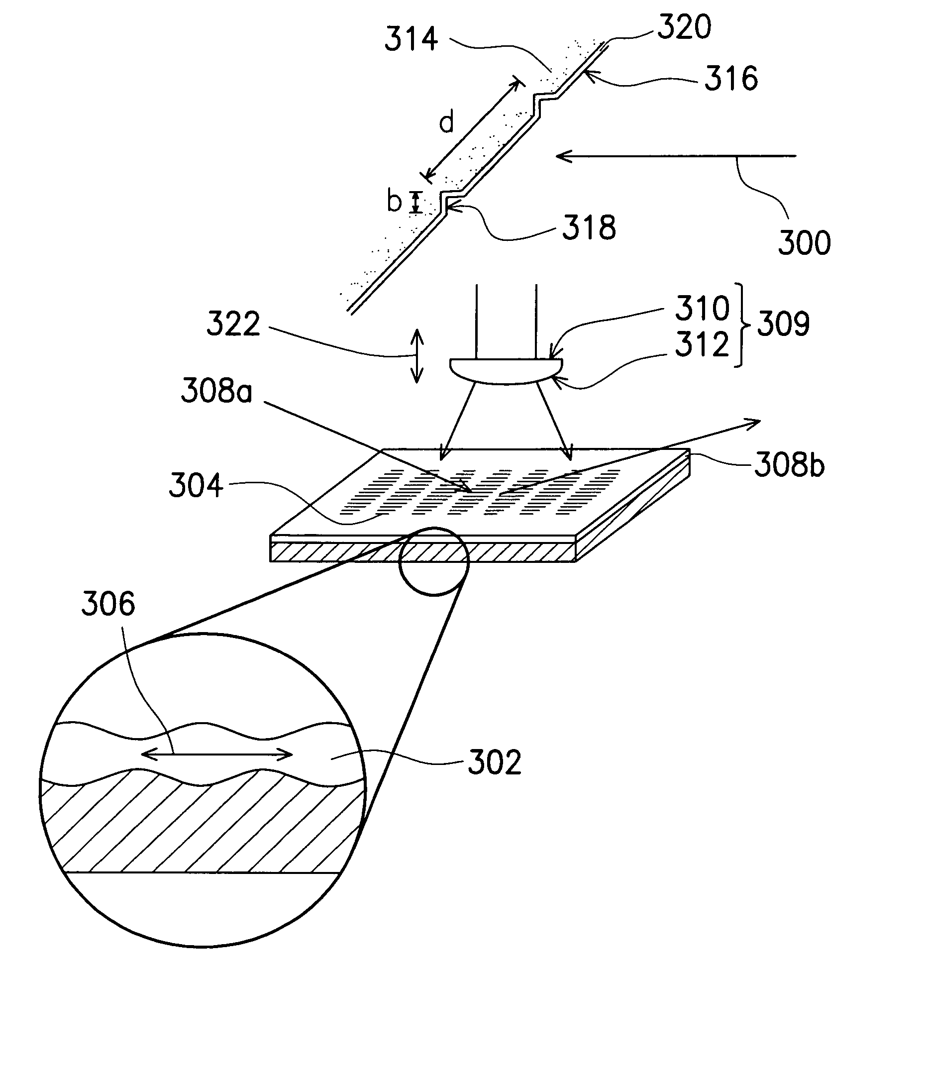
[0031]In this embodiment, the measurement of the thickness of a thin film is used as an illustration. Obviously, the method of forming the laser induced grating pattern is not limited to the thickness measurement of a thin film. In other words, the method of forming a laser induced grating pattern can be used inside a transient surface acoustic wave (SAW) device, one type of measuring sensor for material characterization or bio-chemical assay. Material characterization includes measuring the material properties of a thin film or the material properties of a fluidic compound. Bio-chemical assay includes applications such as mass loading, mechanical properties, rheological properties, electrical proper...


PUM


Abstract

A method of forming a laser-induced grating comprising the steps of providing a substrate with a polished surface having a plurality of reflective regions thereon, providing a pulsed layer beam and focusing the beam on the substrate to produce a grating pattern on the substrate.

Description

CROSS-REFERENCE TO RELATED APPLICATION[0001]This application claims the priority benefit of Taiwan application serial no. 91115276, filed Jul. 10, 2002.BACKGROUND OF THE INVENTION[0002]1. Field of Invention[0003]The present invention relates to a method of forming a laser induced grating pattern. More particularly, the present invention relates to the production of a laser induced grating pattern by providing a pulse laser, which is incident to an interference strain / displacement gage (ISDG).[0004]2. Description of Related Art[0005]With rapid progress in semiconductor production technology, integrated circuits continue to shrink and functional performance continues to improve. However, circuit miniaturization and performance improvement demands an increase in the level of integration. Because most integrated circuits are increasingly complicated, a multi-layer design is frequently required. In the fabrication of integrated circuits, processes including material deposition, photolith...

Claims


Application Information

Patent Timeline
IPC IPC(8): G02B6/34G02B6/124G02F1/11
CPCG02F1/11G02B6/124
Inventor LIAW, JIANN-SHUOH
Owner RITDISPLAY
Why Eureka
Try Eureka