Versatile satellite-type printing press

Inactive Publication Date: 2005-06-02
SHINOHARA MACHINERY
View PDF5 Cites 2 Cited by
  • Summary
  • Abstract
  • Description
  • Claims
  • Application Information

AI Technical Summary

Benefits of technology

[0008] In view of above-described problems of prior art technique, the present invention provides an improved sate

Problems solved by technology

But, according to the prior art technique of series-type press, a great deal of time is required for such modification of press structure, because cylinders must be re-installed in the bearing hole

Method used


Image

  • Versatile satellite-type printing press
  • Versatile satellite-type printing press
  • Versatile satellite-type printing press

Examples


Embodiment Construction

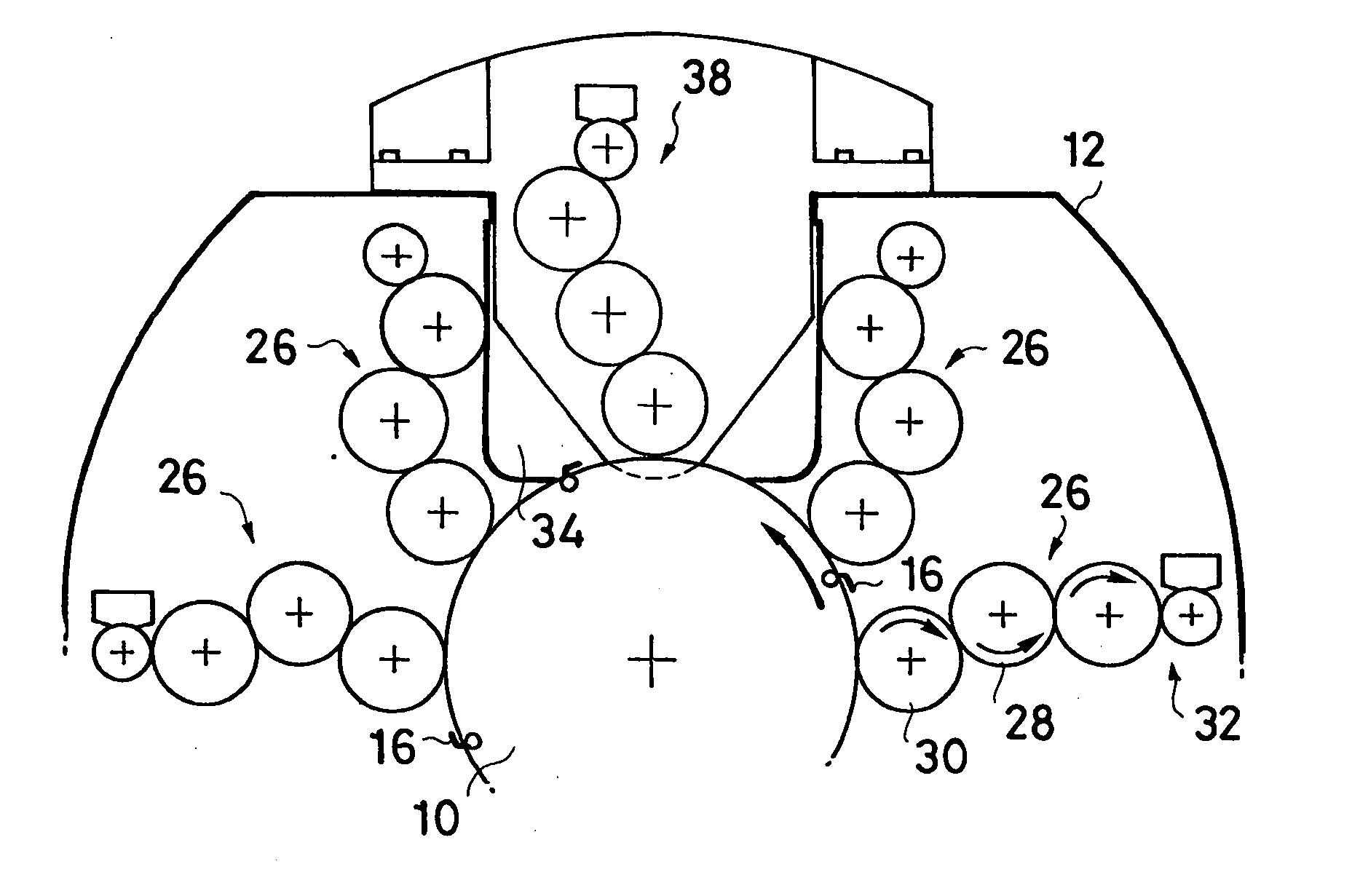
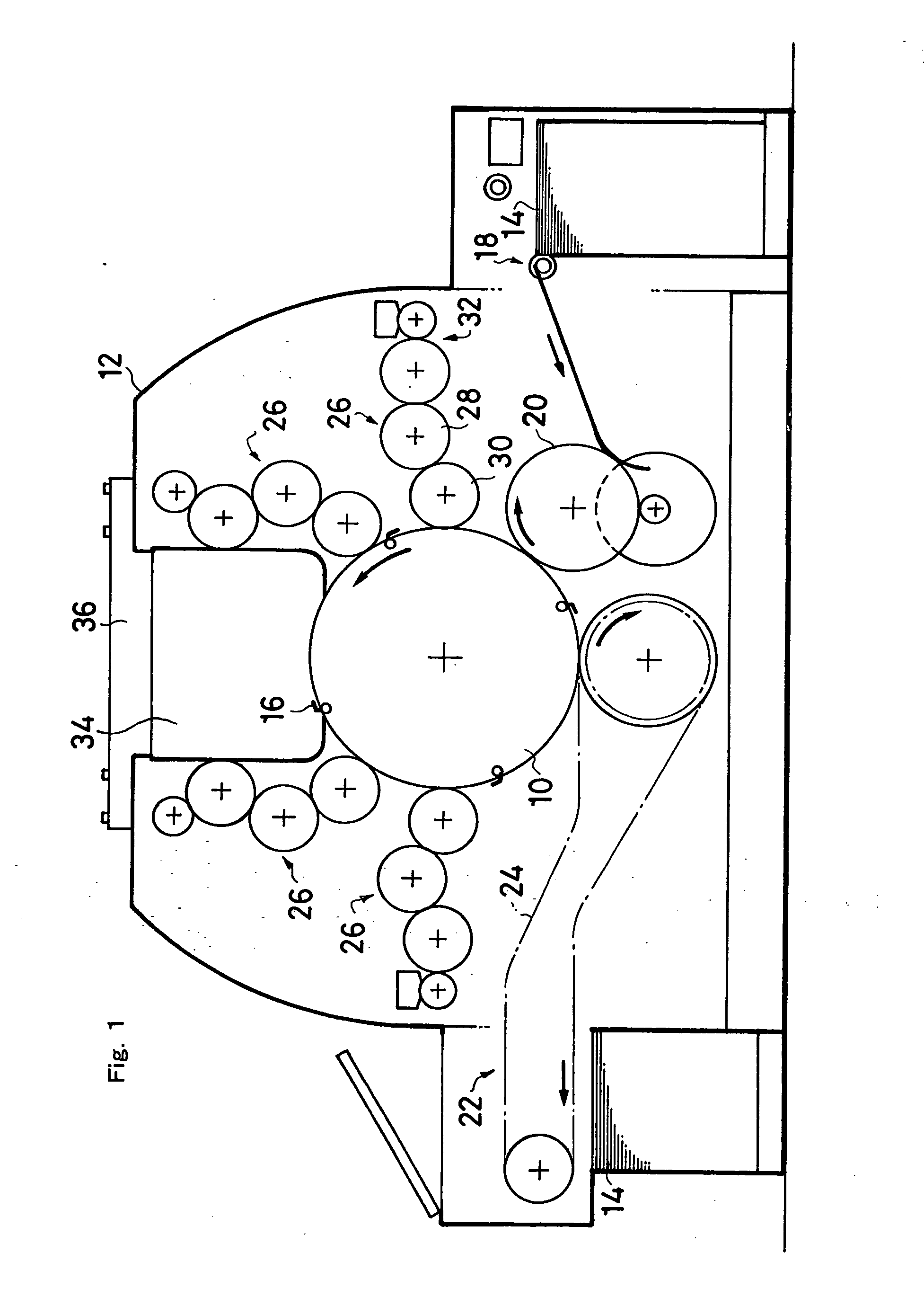
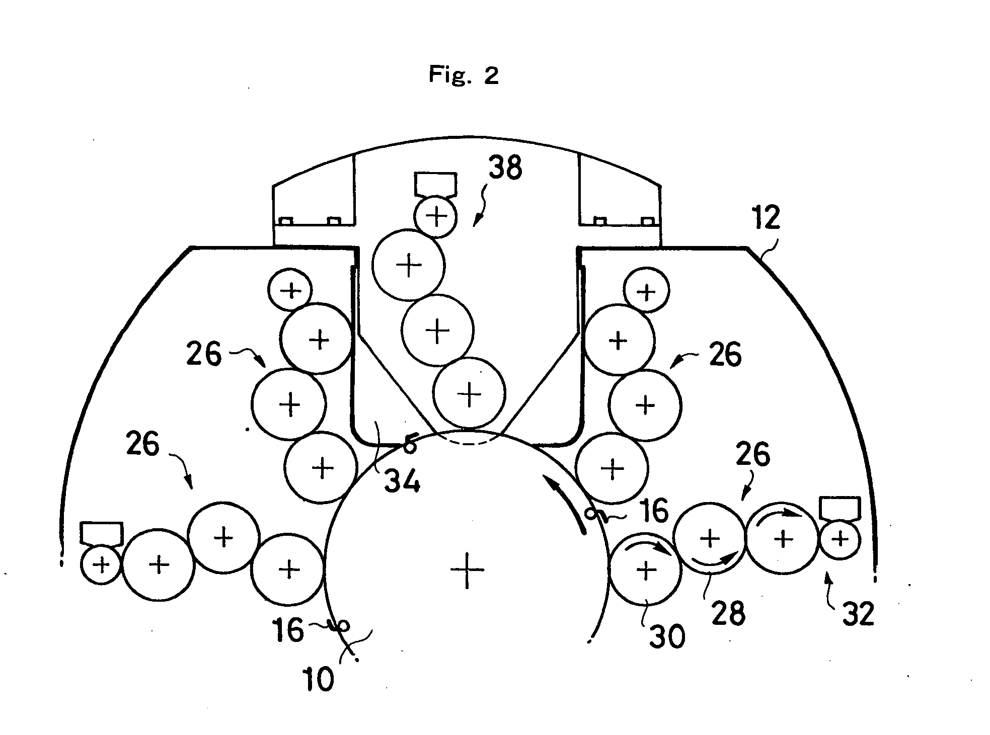
[0020] In the center of FIG. 1, common pressure cylinder 10 of relatively large diameter is shown which is rotatably supported between a pair of side frames 12 of printing press and is driven by motor (not shown). Several grippers 16 which grip the end of sheet 14 are equipped on the periphery of common pressure cylinder 10. The common pressure cylinder 10 is a base for accepting sheet 14 from feeding cylinder 20 of sheet feeder 18 in the upper stream and, after printing, for delivering the printed sheet to delivery chain 24 of sheet delivery device 22 in the lower stream.

[0021] Four sets of fixed printing units 26 are provided around common pressure cylinder 10 in satellite-like manner. In order to perform offset printing, these fixed printing units 26 have plate cylinders 28 equipped with printing plates and blanket cylinders 30 to transfer images. Additionally, inking device 32 is attached to plate cylinder 28. The diameter of common pressure cylinder 10 around which the fixed p...


PUM


Abstract

The present invention relates to sheet-fed satellite-type printing press and aims at versatile satellite-type press by which printing mode can easily be modified.
For this purpose, a part of side frames (12) corresponding to the circumference of common pressure cylinder (10) is cut out to form common installing portion (34) and printing unit (38) or sheet perfecting unit (40) can be installed into the common installing portion (34). Thereby, multi-color printing or perfecting printing can be performed at will.

Description

BACKGROUND OF THE INVENTION [0001] 1. Field of the Invention [0002] The present invention relates generally to satellite-type printing press, or more precisely, to versatile satellite-type press by which printing mode can easily be modified. [0003] 2. Description of the Prior Art [0004] Satellite-type printing press is known where many printing units (for example, four color units) are provided in satellite-like manner around common pressure-cylinder of large diameter. Such satellite-type printing press is a new step toward corresponding to the need of multi-sort short run color printing. [0005] With regard to such satellite-type press, it will surely be convenient if printing mode can be modified at will in compliance with the circumstances of press user. For example, printing unit can be added or sheet perfecting function can be intervened. [0006] In Japanese published unexamined patent specification No. 255434 / 1985, plurality of bearing holes are bored through side frames for sup...

Claims


Application Information

Patent Timeline
IPC IPC(8): B41F7/10B41F13/00B41F21/10
CPCB41F7/10B41F21/106B41F13/0024
Inventor IWAMOTO, MASAYUKI
Owner SHINOHARA MACHINERY
Why Eureka
Try Eureka