Eureka AIR delivers breakthrough ideas for toughest innovation challenges, trusted by R&D personnel around the world.

Catheter balloon and method for forming same

a catheter and balloon technology, applied in the field of intravascular medical devices, can solve the problems of reducing affecting so as to improve the compliance and rupture properties, enhance the performance of the catheter balloon, and maintain the effect of the targeted balloon performance level

Active Publication Date: 2012-03-15
ABBOTT CARDIOVASCULAR
View PDF0 Cites 50 Cited by
  • Summary
  • Abstract
  • Description
  • Claims
  • Application Information

AI Technical Summary

Benefits of technology

"The present invention improves the performance of catheter balloons by enhancing their compliance and rupture properties for a given wall thickness or by maintaining targeted balloon performance levels while reducing wall thickness. This is achieved by reducing the outer diameter of the extruded tube, which leads to improved balloon performance in rupture strength and compliance modulus. The invention also reduces the blow-up ratio of the balloon by controlling the elongation to failure of the extruded tube, which allows for single-stage balloon expansion. Additionally, the invention can improve the balloon's folded profile by reducing wall thickness within its tapers and shafts."

Problems solved by technology

Substantial, uncontrolled expansion of the balloon against the vessel wall can cause trauma to the vessel wall.
In such angioplasty procedures, there may be restenosis of the artery, i.e. reformation of the arterial blockage, or obstructions that cannot be resolved by inflation of the balloon alone.
Above a critical BUR for a selected polymer, the balloon blowing process becomes unstable and the polymer tubing will rupture or tear before a balloon is fully formed.
This results in a rapid increase in the wall hoop stress σh during constant pressure blowing.
If the wall hoop stress of the growing balloon exceeds the ultimate hoop strength of the material, rupture will occur.
This phenomena limits the maximum attainable BUR for a given polymeric material forming the balloon layer.
However, noncompliant balloons generally have relatively low flexibility and softness, making it challenging to provide a low compliance balloon with high flexibility and softness for enhanced catheter trackability.
A compromise is typically struck between the competing considerations of softness / flexibility and noncompliance, which, as a result, has limited the degree to which the compliance of catheter balloons can be further lowered.

Method used


Image

  • Catheter balloon and method for forming same
  • Catheter balloon and method for forming same
  • Catheter balloon and method for forming same

Examples


example

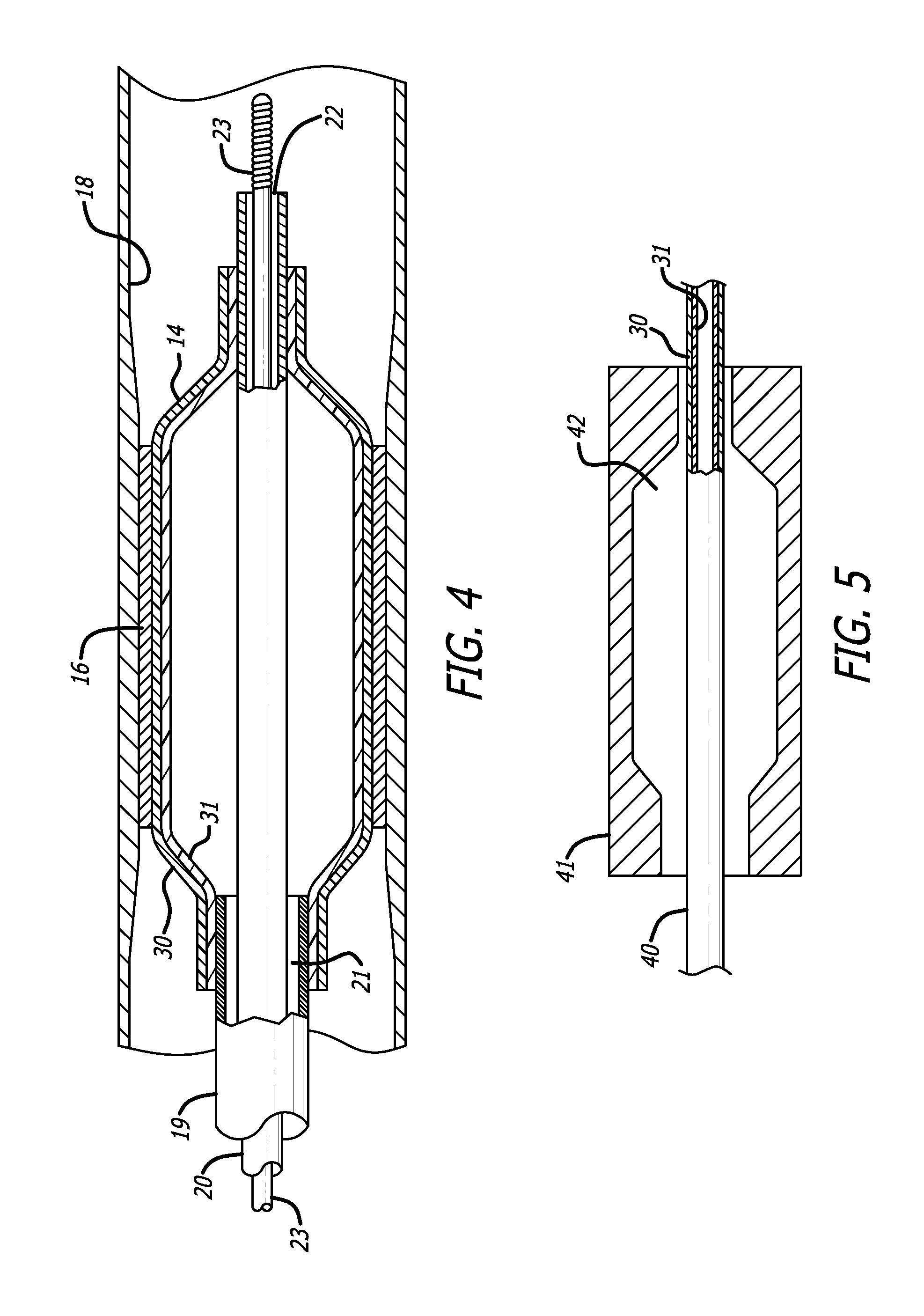
[0094]A variety of experiments have been performed using 3.0 mm 2nd stage balloon molds, dual-layer balloon tubing (Pebax 63D inner, Pebax 72D outer) and the double-blow process with various 1st-stage balloon mold sizes. The highest degree of success is attained by extruding balloon tubing to the same ID as conventional tubing, but with a smaller OD, and correspondingly reducing the area draw down ratio (ADDR) resulting from a 2nd stage balloon expansion so that the wall thickness within the working length matches that of a conventional 3.0 mm balloon.

[0095]The target range for % elongation to failure of conventional as-extruded balloon tubing (ca. 225%) does not work well for the present invention. Consequently, the actual ADDR's resulting from 2nd stage balloon expansion were too high in initial experiments, which led to inadequate wall thickness and abnormally low rupture values. However, analysis of the balloon compliance test data showed that, despite undesirably low ruptures, ...


PUM

PropertyMeasurementUnit
temperatureaaaaaaaaaa
pressuresaaaaaaaaaa
durometer hardnessaaaaaaaaaa

Abstract

A catheter balloon and method involves extruded tubing with multiple layers of different durometer values, selected such that the blow up ratio (BUR) at the balloon's inner surface is increased. In one method a two stage blow mold process uses a small radius initial stage where radial growth is limited, followed by a second stage to a final dimension. A single stage blow mold process is also disclosed where the materials and processing are selected to approach the elongation to failure limit of the material. The single stage approach is preferably followed by a modified post-expansion heat set treatment to promote greater axial strength, leading to a preferred failure mode in the axial rather than radial direction.

Description

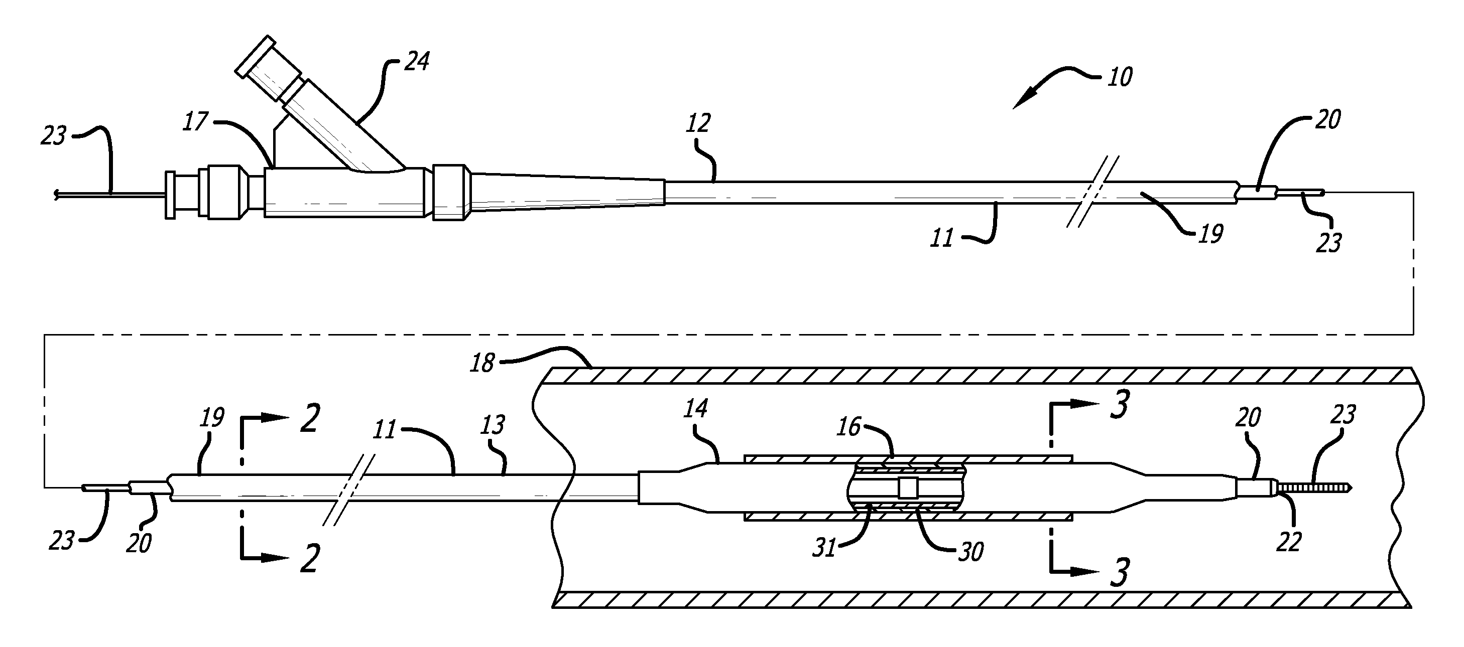
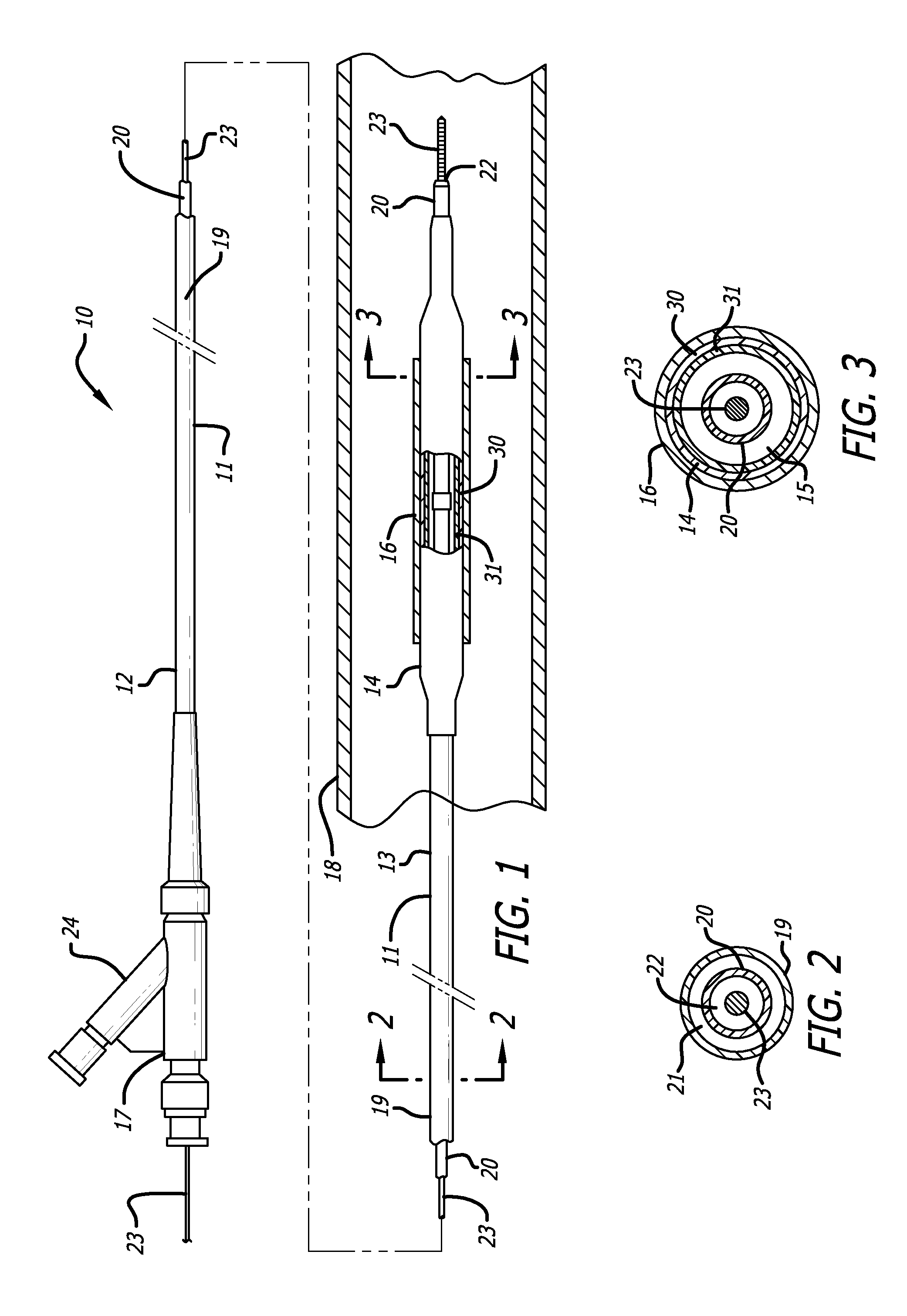
BACKGROUND [0001]The invention relates to the field of intravascular medical devices, and more particularly to an improved balloon for a catheter.[0002]In percutaneous transluminal coronary angioplasty (PTCA) procedures, a guiding catheter is advanced until the distal tip of the guiding catheter is seated in the ostium of a desired coronary artery. A guidewire, positioned within an inner lumen of a dilatation catheter, is first advanced out of the distal end of the guiding catheter into the patient's coronary artery until the distal end of the guidewire crosses a lesion or obstruction to be dilated. The dilatation catheter having an inflatable balloon on the distal portion thereof is then advanced into the patient's coronary anatomy, over the previously introduced guidewire, until the balloon of the dilatation catheter is properly positioned across the lesion or obstruction. Once properly positioned, the dilatation balloon is inflated with liquid one or more times to a predetermined...

Claims


Application Information

Patent Timeline
Patent Type & Authority Applications(United States)
IPC IPC(8): A61F2/84A61L29/04B29C49/04A61M25/10
CPCY10T428/1352A61M25/0009A61L29/14Y10T428/1386A61M2025/1075A61L2420/08B29C49/185A61M25/104A61M25/1029Y10T428/1393A61F2/958B29C49/04A61L29/04B29L2031/7543Y10T428/1334B29C49/22B29C49/18A61M25/10A61M25/1027A61L29/06
Inventor SIMPSON, JOHN A.NELSON, SARAH A.DURCAN, JONATHAN P.
Owner ABBOTT CARDIOVASCULAR
Why Eureka
Eureka Blog
Learn More