Metal split bearing compression load ball joint

a technology of ball joint and split bearing, which is applied in the direction of mechanical equipment, transportation and packaging, couplings, etc., can solve the problems of erratic steering or excessive looseness, rapid deformation of the performance of the movable socket or ball joint, and play in the vehicle suspension system, so as to achieve a constant wear surface

Active Publication Date: 2011-11-01
FEDERAL MOGUL WORLD WIDE LLC
View PDF27 Cites 34 Cited by
  • Summary
  • Abstract
  • Description
  • Claims
  • Application Information

AI Technical Summary

Problems solved by technology

Due to the different axial loads on the stud member, different ball joint designs are required for each category, which are generally not interchangeable.
Movable sockets or ball-joints employed in these applications are subjected to various operating conditions, and may be required to carry substantial loads.
When wear develops, particularly in polymeric bearings, the performance of the movable socket or ball-joint rapidly degrades and, in the case of automotive applications, may result in erratic steering or excessive looseness and play in the vehicle suspension system.

Method used


Image

  • Metal split bearing compression load ball joint
  • Metal split bearing compression load ball joint
  • Metal split bearing compression load ball joint

Examples


Embodiment Construction

[0017]The following detailed description illustrates the invention by way of example and not by way of limitation. The description clearly enables one skilled in the art to make and use the invention, describes several embodiments, adaptations, variations, alternatives, and uses of the invention, including what is presently believed to be the best mode of carrying out the invention.

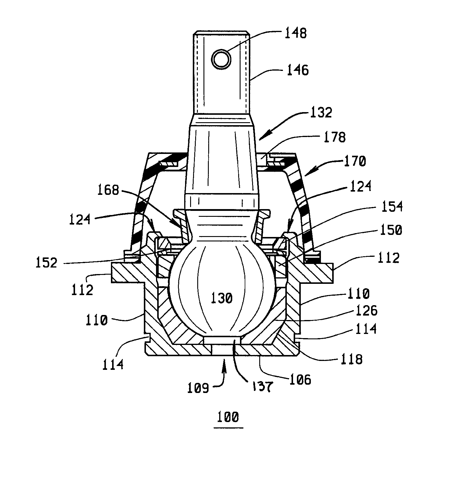
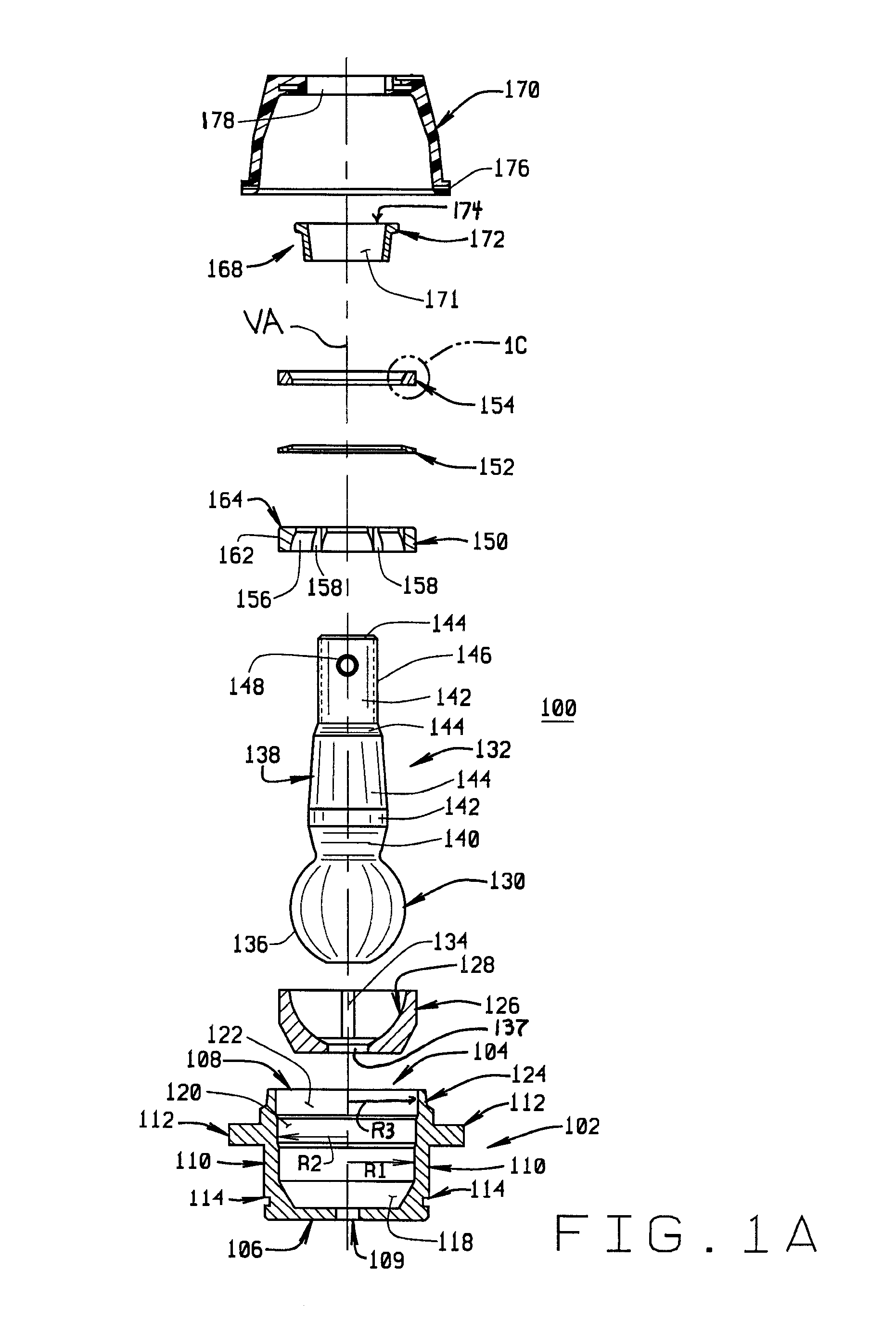
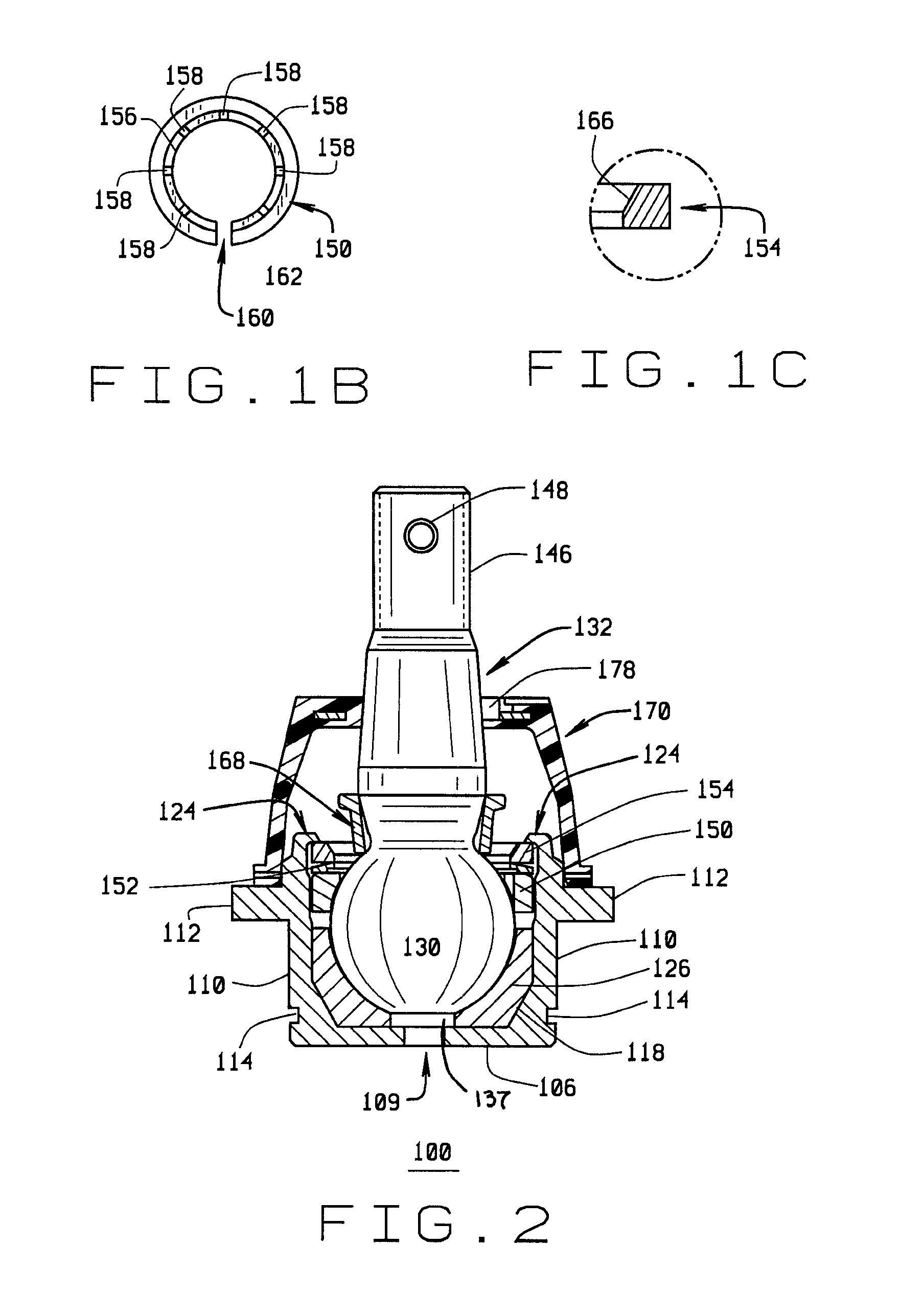
[0018]Turning to FIG. 1A, a movable joint 100 of the present invention is shown in an exploded view. A metal housing 102, within which the various internal components of the movable joint 100 are enclosed, is generally cylindrical, with a central bore 104 defining a side wall having a closed lower end 106 and an open upper end 108. A lubrication or wear indicator passage 109 may be axially disposed in the closed lower end 106, providing access to the central bore 104 after assembly of the movable joint 100. The exterior surface 110 of housing 102 may follow the general contour of the central bore 104. In ...


PUM


Abstract

An improved compression load ball joint assembly consisting of a metal housing having an open end and an internal cylindrical chamber which at least partially encloses a portion of a movable stud member, a lower metal bearing, an upper metal split bearing, and a Belleville washer. The upper metal split bearing is disposed opposite the lower metal bearing to engage the movable stud member and the housing simultaneously. The upper metal split bearing is configured to slide within the housing to provide for a constant wear surface against the movable stud member. The lower metal bearing, upper metal split bearing, Belleville washer, and movable stud member are contained within the housing by a cover plate concentrically disposed about the movable stud member and secured within the open end of the housing.

Description

CROSS-REFERENCE TO RELATED APPLICATIONS[0001]Not Applicable.STATEMENT REGARDING FEDERALLY SPONSORED RESEARCH[0002]Not Applicable.BACKGROUND OF THE INVENTION[0003]The present invention relates to ball joint bearings, and in particular, to an improved all metal compression load ball joint utilizing a split upper bearing configured to provide a bearing surface for the top and sides of a ball stud, and to allow full engagement of the bearing with the housing and the stud simultaneously.[0004]Conventional ball joints, and other movable sockets are used, for example, in automotive steering and suspension applications, and can be divided into two categories. The first category is for use in follower and tension load applications in which the stud member of the ball joint experiences axial tension loads, while the second category is for use in compression load applications in which the stud member of the ball joint experiences axial compression loads. Due to the different axial loads on the...

Claims


Application Information

Patent Timeline
Patent Type & Authority Patents(United States)
IPC IPC(8): F16C11/00F16C11/06
CPCF16C11/069Y10T403/32737Y10T403/32713Y10T403/32631F16C11/0628F16C11/0647F16C2326/05F16C2326/24
Inventor SELLERS, ROGER G.PARKER, GLEN C.BYRNES, THOMAS J.
Owner FEDERAL MOGUL WORLD WIDE LLC
Why Eureka
Try Eureka