Transmission apparatus and method for MIMO system

a technology of transmission apparatus and mimo system, which is applied in the field of wireless communication system, can solve the problems of reducing the bit error rate (ber) performance in a high signal-to-noise ratio (snr) environment, increasing the complexity of the transceiver, and suffering an abrupt change in performance, so as to improve the multiplexing gain and maintain the diversity gain. , the effect of simple coding process

Active Publication Date: 2011-11-01
SAMSUNG ELECTRONICS CO LTD
View PDF16 Cites 7 Cited by
  • Summary
  • Abstract
  • Description
  • Claims
  • Application Information

AI Technical Summary

Benefits of technology

[0014]The present invention is provided to substantially solve at least the above problems and / or disadvantages. It is, therefore, an object of the present invention to provide a transmission apparatus and method for improving multiplexing gain while maintaining the diversity gain available in the conventional spatial diversity technique, through a simple coding process.
[0016]It is further another object of the present invention to provide a transmission apparatus and method for improving multiplexing gain and adjusting diversity gain without increasing complexity of a decoder.
[0017]It is still another object of the present invention to provide a transmission apparatus and method for maximizing system performance by adjusting multiplexing gain and diversity gain according to environment, without increasing complexity.

Problems solved by technology

However, the BLAST scheme, as it provides no diversity gain, there is a decrease in bit error rate (BER) performance in a high signal-to-noise ratio (SNR) environment, and it suffers an abrupt change in performance depending on the type of receiver and transmission optimization technique.
However, because a transmission technique for spatial multiplexing and a transmission technique for spatial diversity are different from each other in design, supporting both of the transmission techniques for spatial multiplexing and spatial diversity within one system causes an increase in complexity of transceivers.

Method used


Image

  • Transmission apparatus and method for MIMO system
  • Transmission apparatus and method for MIMO system
  • Transmission apparatus and method for MIMO system

Examples


Embodiment Construction

[0025]A MIMO transmission apparatus and method according to the present invention will now be described with reference to the accompanying drawings.

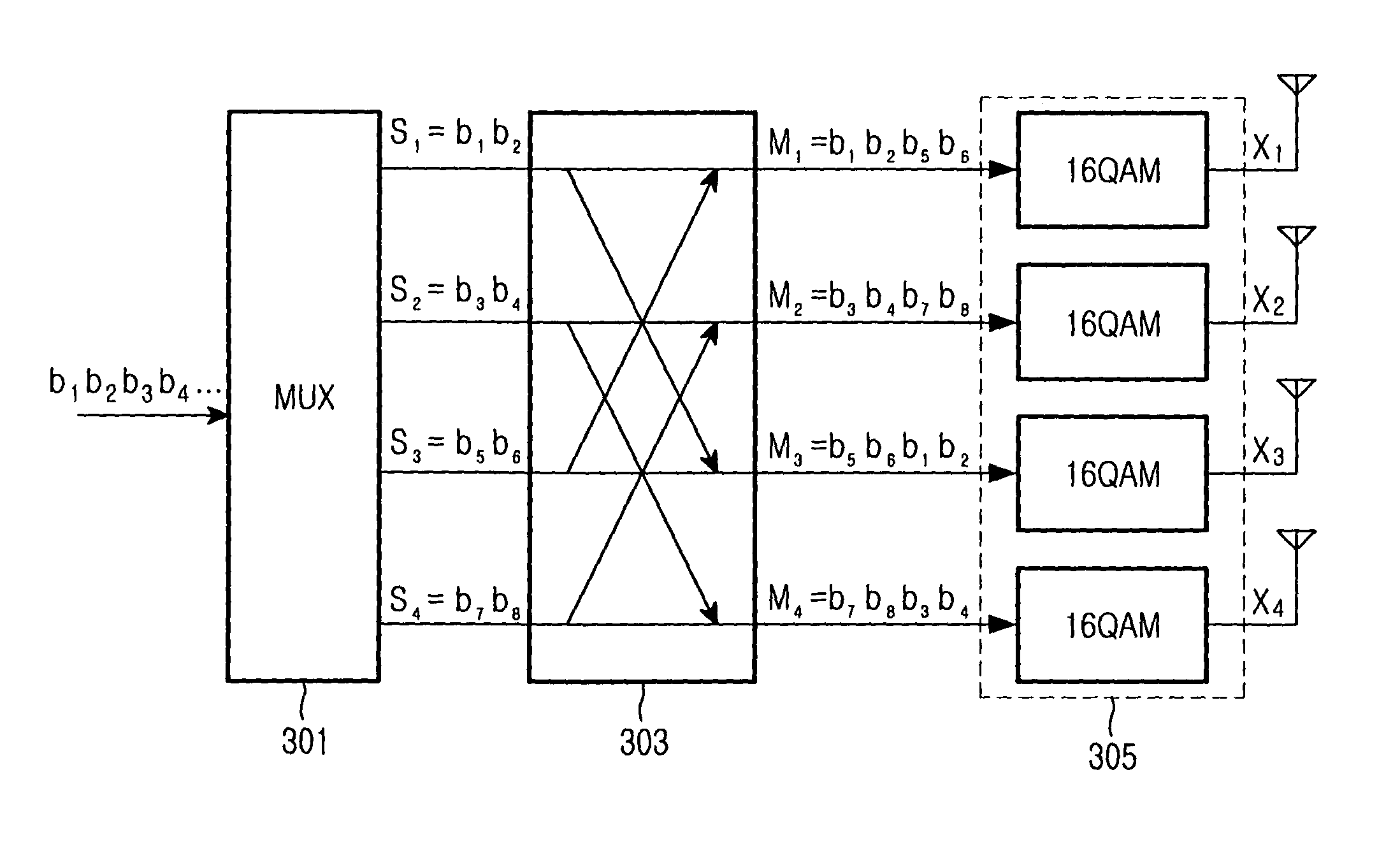
[0026]FIG. 3 is a block diagram illustrating a structure of a MIMO transmission apparatus according to the present invention. As illustrated in FIG. 3, a MIMO transmission apparatus according to the present invention includes a multiplexer 301 for multiplexing an input bit stream b1, b2, b3, b4, . . . into a plurality of parallel bit streams S1, S2, S3, and S4, a bit-order rearranger 303 for reordering bits constituting the parallel bit streams into a plurality of reordered bit streams M1, M2, M3, and M4, and a plurality of modulation modules 305 for modulating the reordered bit streams M1, M2, M3, and M4 into transmission symbols X1, X2, X3 and X4 using a predetermined modulation technique and transmitting the transmission symbols X1, X2, X3 and X4 via their associated transmission antennas. The transmission symbols X1, X2, X3 and X4 ma...


PUM

PropertyMeasurementUnit
timeaaaaaaaaaa
transmission methodaaaaaaaaaa
dimensionaaaaaaaaaa

Abstract

A transmitter in a multiple input multiple output (MIMO) communication system is provided. The transmitter includes a multiplexer for multiplexing an input bit stream into a plurality of bit streams, and outputting the bit streams in parallel; a bit-order rearranger for reordering bits constituting the bit streams, which are output from the multiplexer in the same time period, and outputting the reordered bits as reordered bit streams; and a modulator for modulating the parallel reordered bit streams output from the bit-order rearranger according to their associated modulation schemes, and transmitting the modulated symbols via their associated antennas.

Description

PRIORITY[0001]This application claims the benefit under 35 U.S.C. § 119(a) of an application entitled “Transmission Scheme for MIMO System” filed in the Korean Intellectual Property Office on Feb. 2, 2005 and assigned Serial No. 2005-9561, the entire contents of which are incorporated herein by reference.BACKGROUND OF THE INVENTION[0002]1. Field of the Invention[0003]The present invention relates generally to a wireless communication system, and in particular, to a transmission scheme for a Multiple Input Multiple Output (MIMO) communication system.[0004]2. Description of the Related Art[0005]In a MIMO communication system that transmits / receives data using a plurality of transmission antennas and reception antennas, a MIMO channel formed by the transmission and reception antennas is disassembled into a plurality of independent spatial channels. Each of the spatial channels is mapped to one dimension, and the use of additional dimensions created by the multiple transmission and rece...

Claims


Application Information

Patent Timeline
Patent Type & Authority Patents(United States)
IPC IPC(8): H04L27/00
CPCH04B7/0689H04B7/0691H04B7/0871H04B7/0874H04L1/0071H04L1/06B21J15/40B21J15/30
Inventor NAM, SEUNG-HOONHWANG, CHAN-SOOCHUNG, JAE-HAKJUNG, YOUNG-HOROH, WON-ILCHAE, CHAN-BYOUNG
Owner SAMSUNG ELECTRONICS CO LTD
Why Eureka
Try Eureka