Optical fiber illumination device

an illumination device and optical fiber technology, applied in the direction of fibre light guides, lighting and heating apparatus, instruments, etc., can solve the problems of significant optical coupling loss, loss of light output of light emitting diodes without being coupled with optical fiber arrays, etc., to achieve the effect of minimizing optical coupling loss and color non-uniformity

Inactive Publication Date: 2011-11-08
SAMSUNG ELECTRONICS CO LTD
View PDF9 Cites 0 Cited by
  • Summary
  • Abstract
  • Description
  • Claims
  • Application Information

AI Technical Summary

Benefits of technology

[0012]In accordance with an aspect of the present invention, there is provided an optical fiber illumination device which minimizes optical coupling loss and color non-uniformity.

Problems solved by technology

However, in Satoshi, much of the light output from the light emitting diode is lost without being coupled with the optical fiber array.
Especially in the case where the area of a light receiving end of an optical fiber or an optical fiber array is very small compared to the light divergence angle of a light source, or the area of the light emitting surface of the light source is very large compared to the area of the light receiving end of the optical fiber or the optical fiber array, such optical coupling loss significantly increases.

Method used


Image

  • Optical fiber illumination device
  • Optical fiber illumination device
  • Optical fiber illumination device

Examples


first embodiment

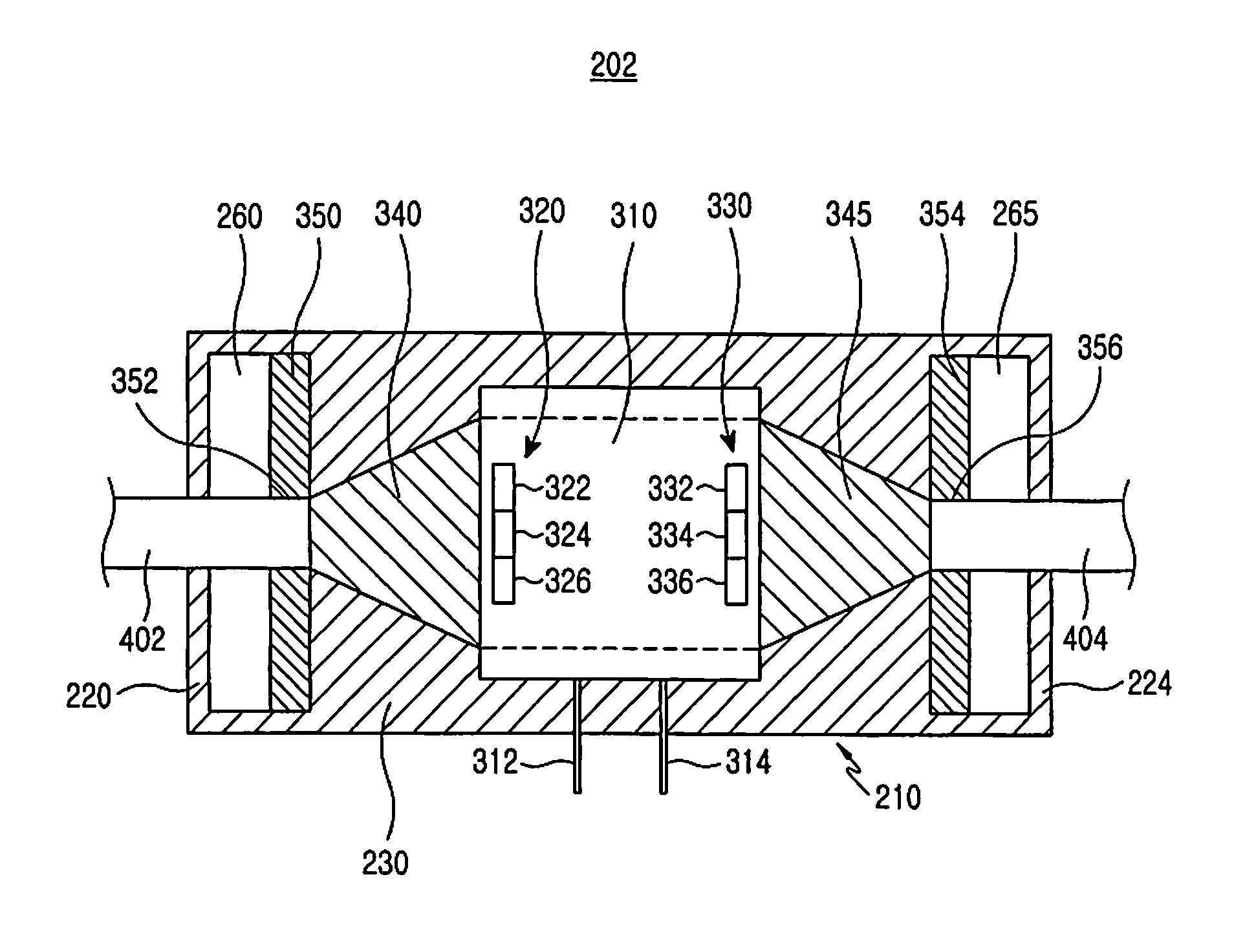
[0045]Meanwhile, unlike the above described first embodiment of the present invention, an open-type optical fiber illumination device may be required according to the design of appliances, such as a mobile phone. An overall rectangular block shape, instead of a cylindrical shape, light source module may be required for slimness of appliances. Also, in order to improve the appearance, a fabricated light source module may be realized in such a manner that it has a cross section of an oval shape, a rectangular shape with round edges (similar to a capsule shape), as well as other shapes.

second embodiment

[0046]Hereinafter, in the present invention, an open-type optical fiber illumination device and a light source module having an overall rectangular block shape will be described, with redundant explanations omitted.

[0047]FIG. 8 is a view illustrating an optical fiber illumination device according to a second preferred embodiment of the present invention. The optical fiber illumination device 500 includes first and second light source modules 502a and 502b, and an optical fiber 700. Each the first light source module 502a and the second light source module 502b includes a pair of connector pins 512a and 514a, or 512b and 514b for connection with an external circuit board (not shown), and is supplied with a control signal and power supply from the external circuit board through the corresponding connector pins 512a and 514a, or 512b and 514b. The first and second light source modules 502a and 502b generate first light and second light, respectively, and rotate the first light and the ...


PUM


Abstract

Disclosed is an optical fiber illumination device including a light source for outputting light; a coupler for converging the light input from the light source through multiple reflection; and an optical fiber to which the converged light is input.

Description

PRIORITY[0001]This application claims priority under 35 U.S.C. §119(a) to an application entitled “Optical Fiber Illumination Device” filed with the Korean Intellectual Property Office on Jul. 30, 2008, and assigned Serial No. 10-2008-0074619, the contents of which are incorporated herein by reference.BACKGROUND OF THE INVENTION[0002]1. Field of the Invention[0003]The present invention relates to an illumination device, and more particularly to an illumination device using an optical fiber.[0004]2. Description of the Related Art[0005]An illumination device using an optical fiber has been recently widely used for interior / exterior designs. The optical fiber illumination device may be used in locations with high humidity or high temperature, because an optical fiber generates no heat, has an excellent moisture-proof / heat-resistant characteristic, and allows the light input from a light source to be transferred to a position far away from the light source. In the case where the light s...

Claims


Application Information

Patent Timeline
Patent Type & Authority Patents(United States)
IPC IPC(8): F21V7/04
CPCG02B6/0006G02B6/001G02B6/4298G02B6/4204G02B6/4249F21V2200/10F21Y2115/10Y10S362/80
Inventor JUNG, SUN-TAELEE, JOO-HOON
Owner SAMSUNG ELECTRONICS CO LTD
Why Eureka
Try Eureka