Hybrid hydraulic drive system with accumulator as the frame of vehicle

a hybrid hydraulic and accumulator technology, applied in the direction of fluid couplings, rotary clutches, couplings, etc., can solve the problems of not necessarily addressing or solving the full energy consumption of those vehicles, series hybrid hydraulic systems, lack of good and precise flow control speed, etc., to achieve safer operation, improve efficiency, and simplify control

Active Publication Date: 2011-12-20
ROSMAN ALLAN
View PDF71 Cites 23 Cited by
  • Summary
  • Abstract
  • Description
  • Claims
  • Application Information

AI Technical Summary

Benefits of technology

[0023]In accordance with one aspect of the invention, there is provided the use of an accumulator which is in whole or in part the frame of the vehicle. Such a configuration potentially overcomes one of the major drawbacks for the implementation of such hydraulics, namely, the large weight and volume per unit of stored energy of the accumulator. At the same time, this aspect of the invention allows for much larger accumulators than were previously possible, since the accumulator weight and volume is no longer as significant a consideration. The utilization of the frame or at least a part thereof as the accumulator allows an increased dimension of the accumulator, and may also allow for periods of operation of the vehicle without the prime mover running, saving on both fuel and emissions, as engines and electric motors consume unloaded about 40% of the maximum consumption or current in the case of the electric motors. It also allows its benefits to be applied to larger vehicles.
[0024]With this much larger accumulator, with a small weight / volume penalty, is now possible to shutoff the engine when the accumulator is full, and in doing so, the vehicle can run several minutes without the engine running, saving a large amount of energy.
[0028]The coordination of the operation of the system, and optimally selective use of the prime mover and accumulator and their relative contribution to the vehicle at any given time, is preferably accomplished with a computer control and programmed software. In one embodiment of the invention, one version of the controls allows for the use of one pedal or joystick to control speed, direction, acceleration and braking. With a joystick being used, the elements of steering can be added, resulting in a vehicle which may be much simpler to control and much safer to operate. Further, the use of a continuous automatic transmission in accordance with an aspect of the invention allows for even greater efficiency and potentially lower emissions.

Problems solved by technology

The parallel hydraulic system may be used as an add-on on vehicles and does not necessarily address or solve the full energy consumption issues of those vehicles.
The conventional series hybrid hydraulic systems go beyond the parallel system, but lack a good and precise flow control speed.
They have not solved, at low or acceptable cost, the recharge of the accumulator using the extra power of the prime mover when this is available.
Both the parallel and the series solutions and devices have a very significant handicap: steel accumulators can weigh more than fifty (50) times the weight of a lead-acid battery per unit of stored energy.
When fiber made accumulators are used, the weight differential is still significant and can be about 12 to 1, but the price of making such as device increases greatly, making it in effect economically unfeasible.
As a result, all or most, accumulators used for present hybrid hydraulic applications are generally quite small and may be usable only for short cycles, mainly for brake energy recuperation and release.
Furthermore, the scenario described above does not allow for those hydraulic systems to actually stop the engine, or the prime mover, when the accumulator is full and has energy available to propel the vehicle, as the vehicle will only run for a few seconds with the relatively small energy content of the accumulator.
The presently available hydraulic systems, with few exceptions, are not configured or built to allow for this type of dual operating mode.

Method used


Image

  • Hybrid hydraulic drive system with accumulator as the frame of vehicle
  • Hybrid hydraulic drive system with accumulator as the frame of vehicle
  • Hybrid hydraulic drive system with accumulator as the frame of vehicle

Examples


Embodiment Construction

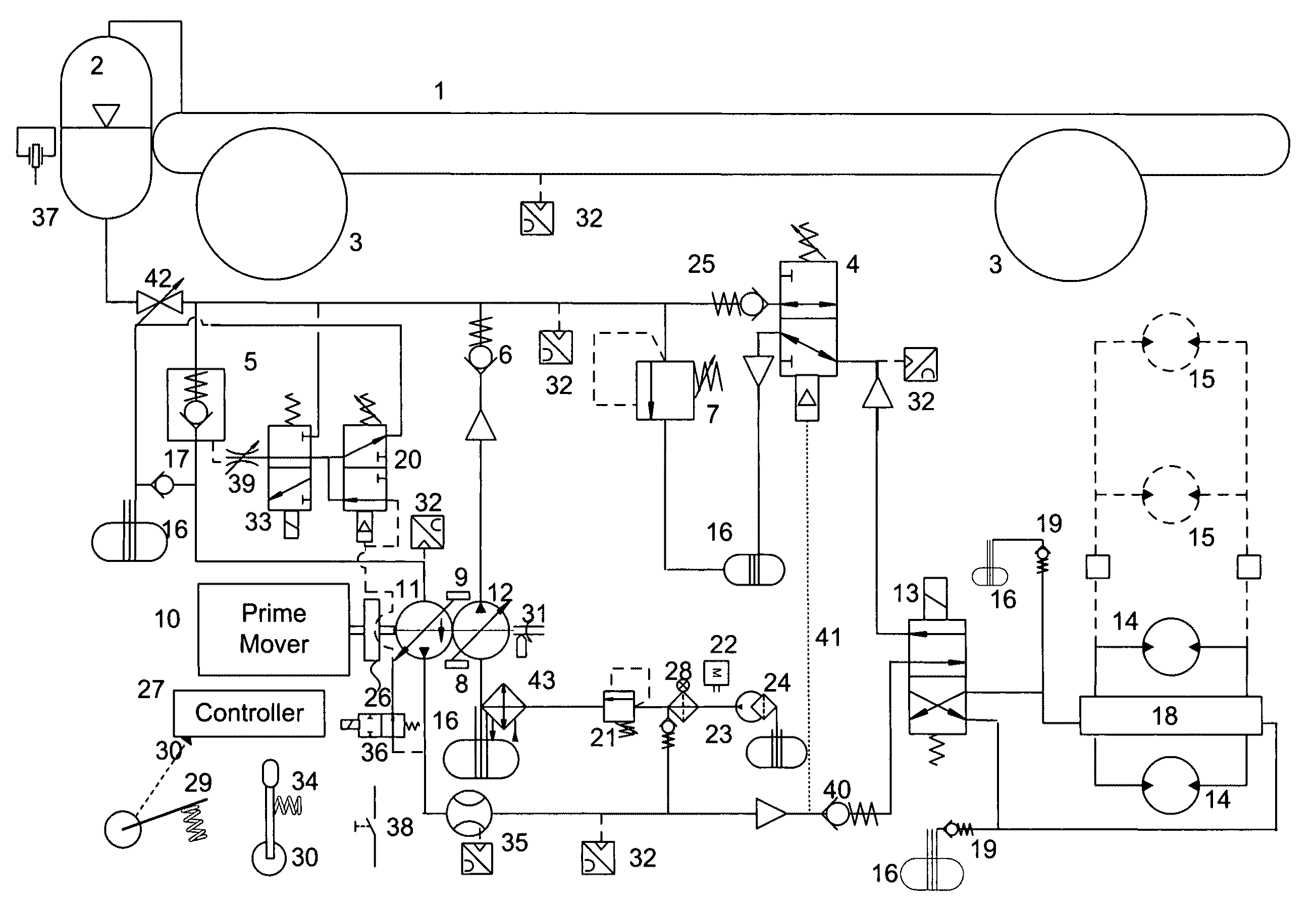
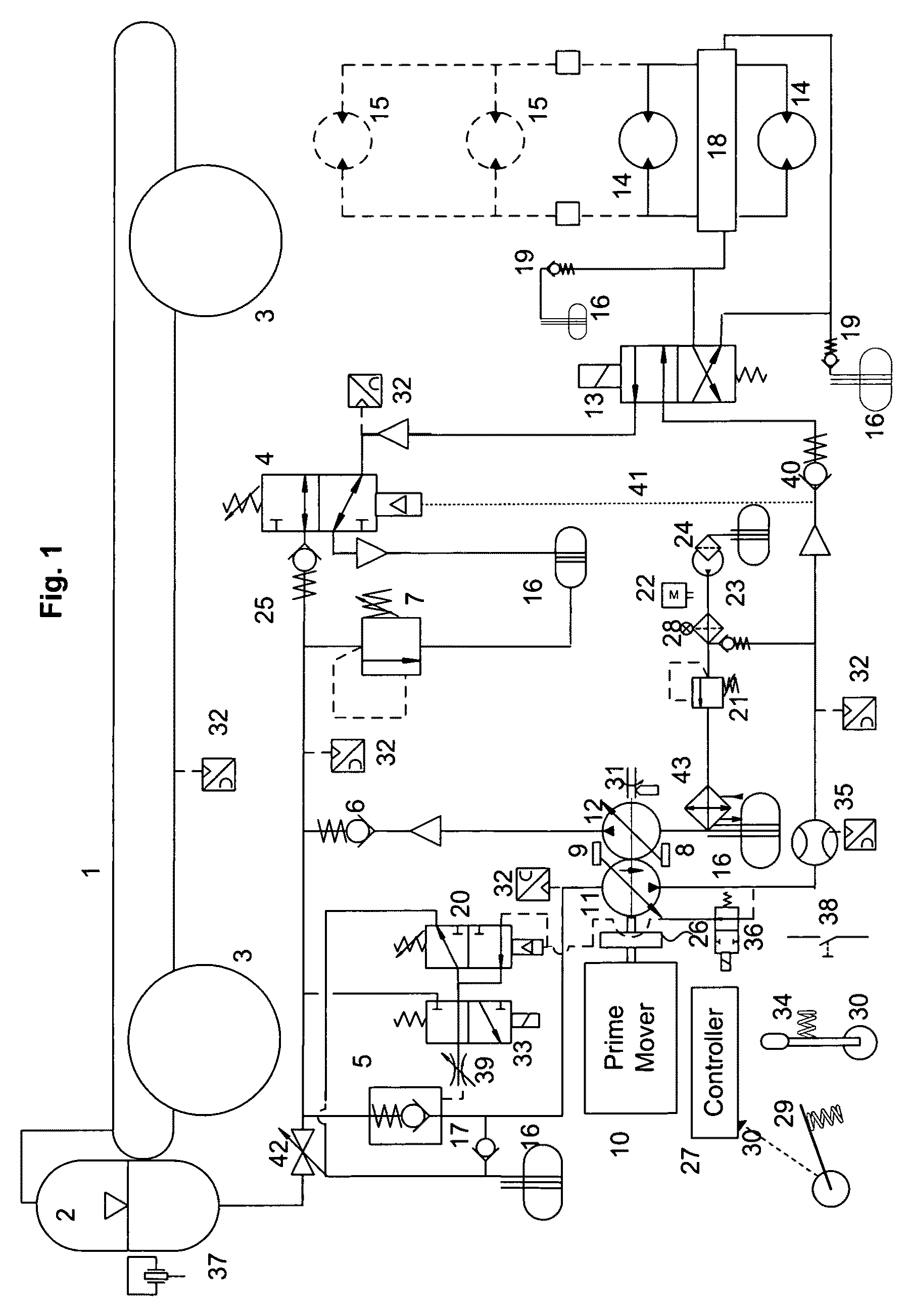
[0033]One preferred embodiment of the present invention is illustrated in FIG. 1 of the drawings. It should be appreciated that the embodiment shown in FIG. 1 of the drawings is representative of a hydraulic schematics, and variations and modifications may be made in accordance with the invention.

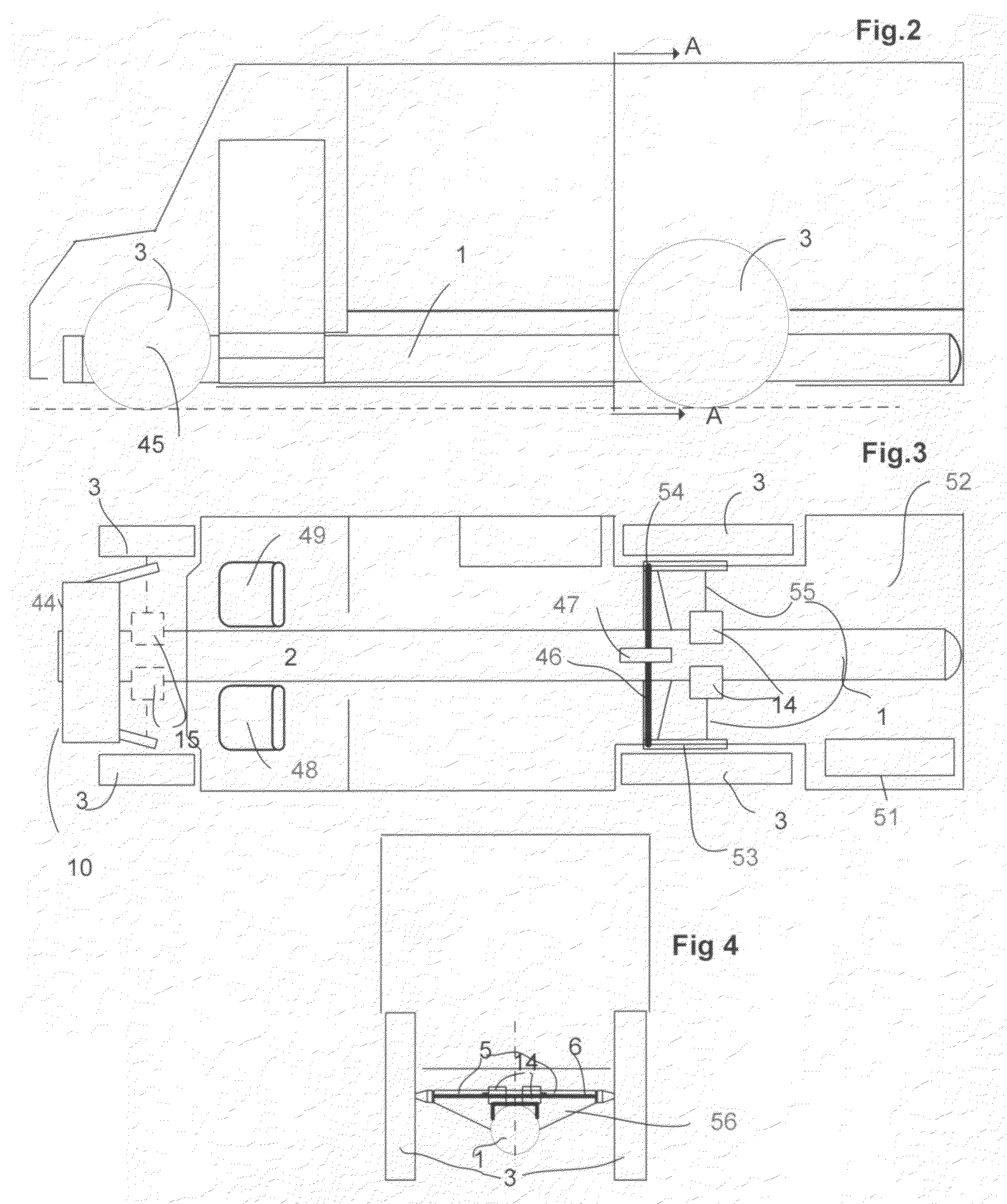
[0034]FIGS. 2, 3 and 4 of the drawings comprise illustrations in schematic format of a vehicle sample application incorporating one preferred embodiment of the system on a commercial van. It should be understood that this is for illustration purposes only and the scope of the invention is not in any way limited by the use of this example. Furthermore, the system of the invention may be used on many types of vehicles as well as vehicles having different types of prime movers, including electric motors and internal combustion engines (ICE).

[0035]With reference to FIG. 1 of the drawings, there is shown a preferred embodiment of one hydraulic circuit which falls within the scope of the inventio...


PUM


Abstract

A hybrid hydraulic power transmission system for all terrestrial's vehicles comprises a prime mover and an accumulator which could also be used as the main load bearing full or partial frame for all those vehicles. A hydraulic power integrator is operatively connected to the prime mover and the accumulator and selectively able to draw power for the vehicle from the prime mover, the accumulator, or a combination thereof.

Description

CROSS-REFERENCE TO RELATED APPLICATIONS[0001]This is a continuation-in part of application Ser. No 12 / 313,046, filed in Nov. 17, 2008 now abandoned.FIELD AND BACKGROUND OF THE INVENTION[0002]The invention relates to a hybrid hydraulic drive system for all types of terrestrial vehicles, including vehicles running on rails, using as prime mover, any rotational device able to give an output torque. A variable hydraulic pump may be connected to the prime mover and acts as a “power integrator”, receiving hydraulic power from the accumulator, mechanical power from the prime mover, or a combination thereof, to supply the desired flow and necessary pressure to the hydraulic motors during operation. A second variable pump reloads the accumulator with the remnant power available, if any, during the whole cycle. The accumulator may be quite large and may also be used partially or totally, as the main load bearing full frame for all terrestrial vehicles. The braking energy may be returned to th...

Claims


Application Information

Patent Timeline
Patent Type & Authority Patents(United States)
IPC IPC(8): B60K6/12
CPCB60K6/12F16H61/4096Y02T10/6208Y02T10/62
Inventor ROSMAN, ALLAN
Owner ROSMAN ALLAN
Why Eureka
Try Eureka