Analytical chemical sampling system with bypass mode

a sampling system and analytical technology, applied in the direction of material analysis, suspensions and porous materials analysis, instruments, etc., can solve the problems of invalid analytical test data, costly repairs and downtime for testing laboratories, and contamination of the entire system, so as to reduce the amount of time

Active Publication Date: 2012-01-10
PROFESSIONAL TECHN SERVICES
View PDF15 Cites 11 Cited by
  • Summary
  • Abstract
  • Description
  • Claims
  • Application Information

AI Technical Summary

Benefits of technology

[0011]Accordingly, it is an advantage of the present invention to provide an apparatus and method of sampling which delivers a vapor sample to an analyzer instrument using a Desorbtion Mode that has a “split flow” characteristic, which allows a greater volume of gas to be delivered to the analyzer instrument using an arrangement that does not increase the amount of water that is delivered to the analyzer instrument.
[0012]It is another advantage of the present invention to provide an apparatus and method of operation that minimizes the amount of time between a bake step at the end of a first sampling cycle and a purge step at the beginning of the next sampling cycle, by using a fan that cools the sparge vessel by thermal convection.
[0013]It is yet another advantage of the present invention to provide an apparatus and method of sampling that uses a thermal convection heater for heating a sparge vessel.
[0014]It is still another advantage of the present invention to provide an apparatus and method of sampling using a sparge vessel, in which a single sensor is provided that can detect both foaming and an overfill condition.
[0015]It is a further advantage of the present invention to provide an apparatus and method of sampling that provides a foam sensor in a sparge vessel, and upon detecting foaming, creates an alternative route for the purge gas that can bypass the frit of the sparge vessel and allow the purge cycle to continue without aborting.
[0016]Additional advantages and other novel features of the invention will be set forth in part in the description that follows and in part will become apparent to those skilled in the art upon examination of the following or may be learned with the practice of the invention.

Problems solved by technology

One problem with purging aqueous samples is they have a tendency to foam, and if the foam is left unattended the sample could come in contact with internal pathway components of the instruments pathway causing contamination to the entire system.
This can require costly repairs and downtime for the testing laboratory, along with rendering the analytical test data invalid.
The problem here is that the sample is then wasted and deemed unusable.
However this treatment can raise concerns regarding the sample integrity.
However the heating of the foam and headspace of the sample containing extracted VOCs could also raise some questions on the integrity of the extracted VOCs.
The pressure and flow rates for the purge and carrier gas usually differ, causing some dead volume issues during the switching of fluidic communication of purge gas pathway to the carrier gas pathway during the desorbtion step.
When sampling an aqueous sample matrix, depending on the carrier gas flow settings and purge and trap desorbtion settings, an unwanted amount of moisture content is sometimes transferred to the gas chromatograph, which affects analytical resolution and detected recovery of the extracted VOCs.

Method used


Image

  • Analytical chemical sampling system with bypass mode
  • Analytical chemical sampling system with bypass mode
  • Analytical chemical sampling system with bypass mode

Examples


Embodiment Construction

[0038]Reference will now be made in detail to the present preferred embodiment of the invention, an example of which is illustrated in the accompanying drawings, wherein like numerals indicate the same elements throughout the views. The exemplification(s) set out herein illustrate(s) at least one preferred embodiment of the invention, in at least one form, and such exemplification(s) (is)(are) not to be construed as limiting the scope of the invention in any manner.

[0039]The terms “first” and “second” preceding an element name, e.g., first inlet, second inlet, etc., are used for identification purposes to distinguish between similar or related elements, results or concepts, and are not intended to necessarily imply order, nor are the terms “first” and “second” intended to preclude the inclusion of additional similar or related elements, results or concepts, unless otherwise indicated.

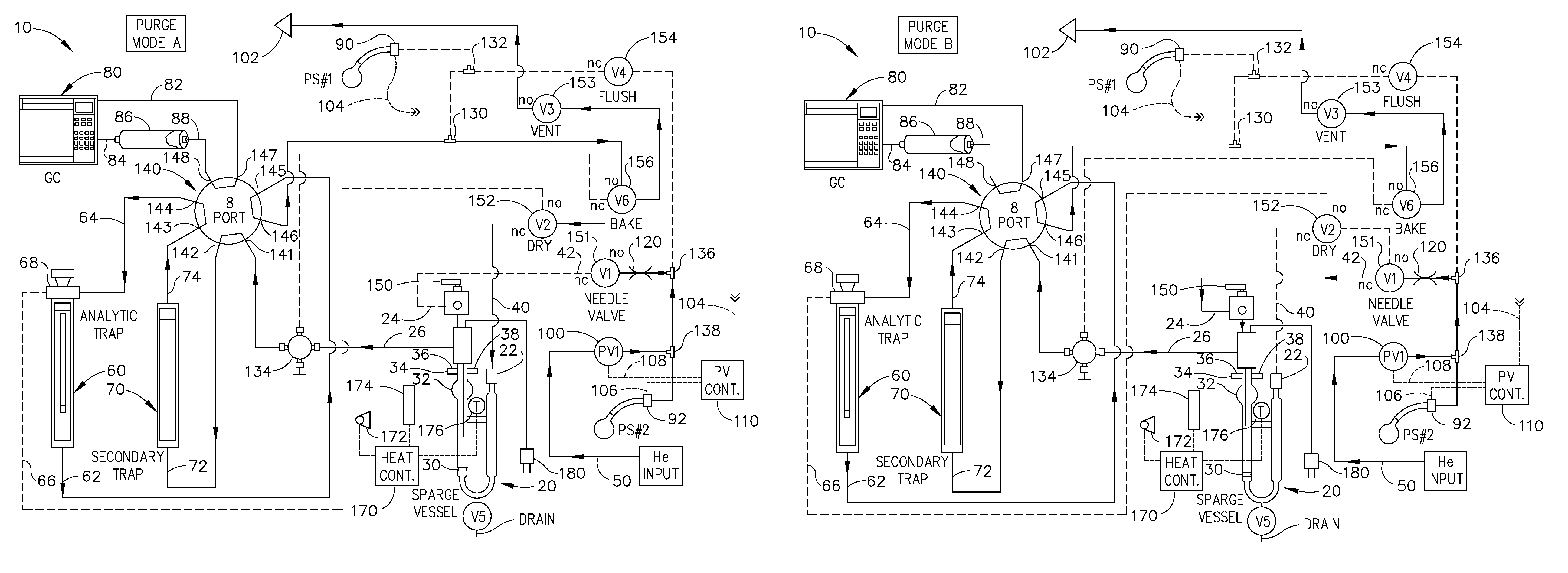
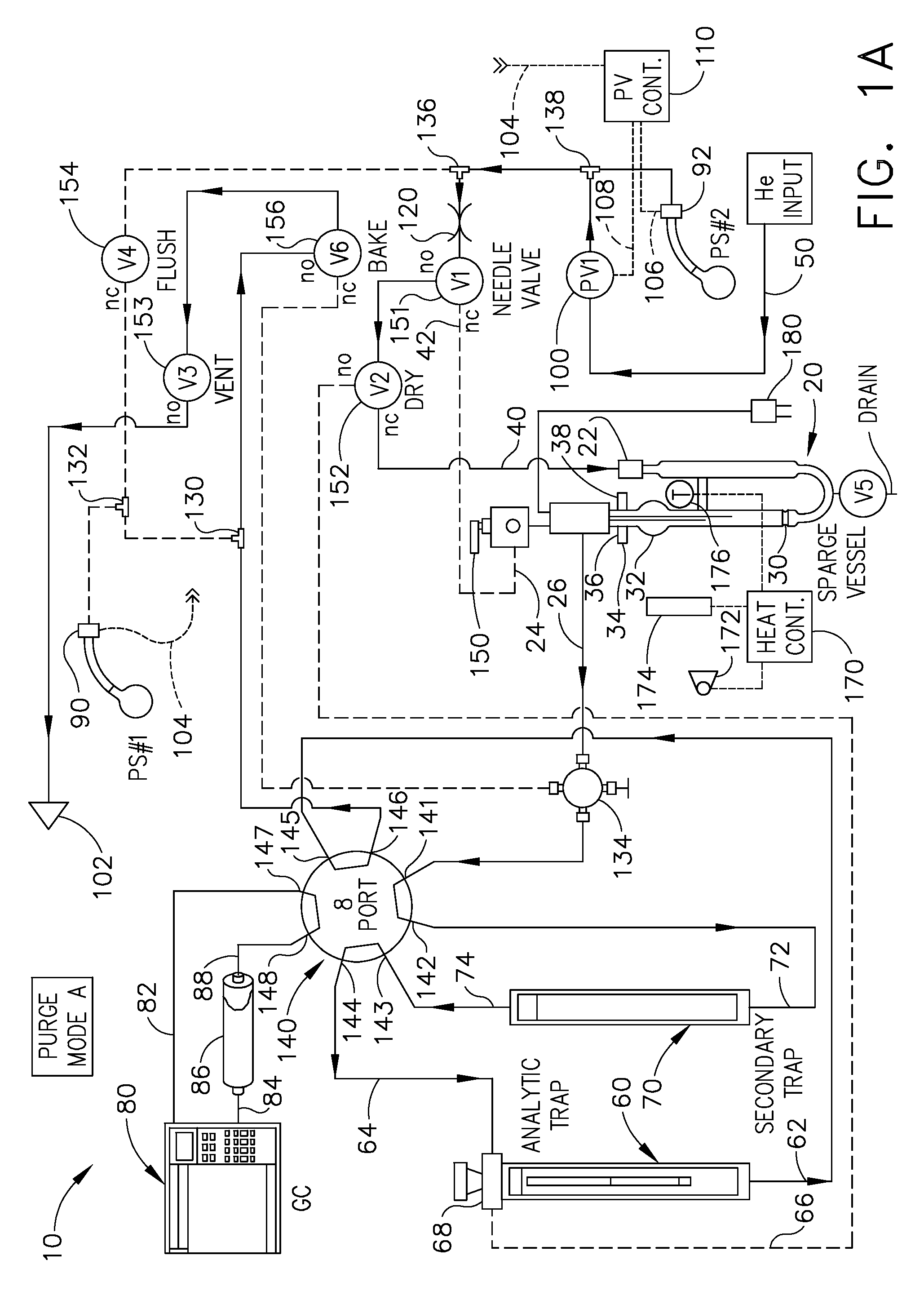
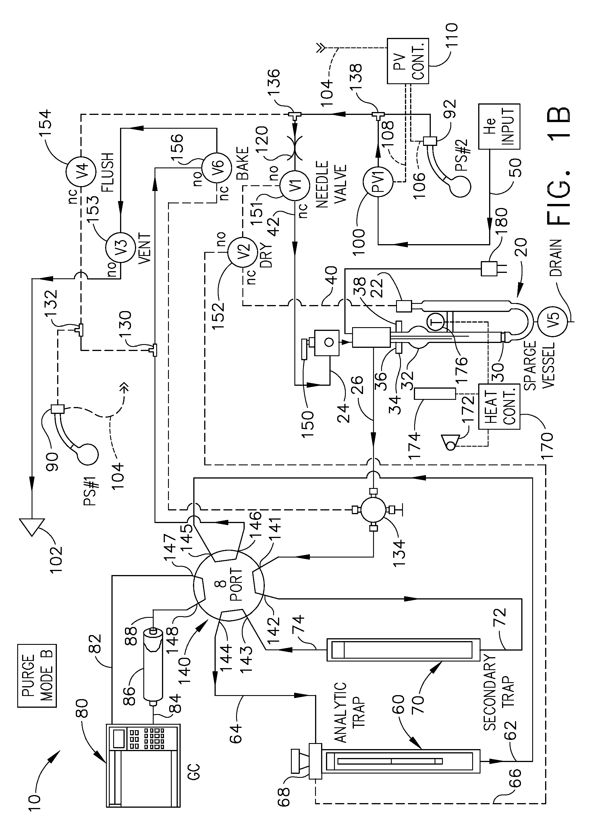
[0040]Referring now to FIG. 1A, a fluidic schematic diagram is provided, generally designated by the...


PUM

PropertyMeasurementUnit
inner diameteraaaaaaaaaa
lengthaaaaaaaaaa
analytical chemical sampling apparatusaaaaaaaaaa

Abstract

A purge and trap concentrator system that includes a sparge vessel, and includes a variable gas flow valve for controlling the gas pressure in an analytic trap or the sparge vessel; a sensor that detects both a foaming sample state and a high liquid level in the sparge vessel, using one optical sensor; a control scheme that re-directs the purge gases to a second inlet of the sparge vessel during a foaming condition; a control scheme that uses a split flow to enhance the quantity of sample gases passed from an analytic trap; an electrically powered thermal energy source with a fan raising the sparge vessel temperature via thermal convection.

Description

BACKGROUND OF THE INVENTION[0001]1. Field of the Invention[0002]The present invention relates to purge and trap concentrator systems, and, more particularly, to those that include a sparge vessel. The invention, in various embodiments, includes: (1) a variable gas flow valve for controlling the gas pressure in the sparge vessel, or in an analytic trap; (2) a foam sensor subassembly that detects both a foaming sample state and a high liquid level in the sparge vessel, using a single optical sensor; (3) a control scheme in which a purge and sampling procedure can continue after a foaming sample has been detected, by re-directing the purge gases to a second inlet of the sparge vessel; (4) a control scheme in which a desorbtion mode uses a split flow to enhance the quantity of sample gases that are passed to an analyzer instrument from an analytic trap; (5) a thermal heater subassembly that uses an electrically powered thermal energy source and a fan to raise the temperature of the spar...

Claims


Application Information

Patent Timeline
Patent Type & Authority Patents(United States)
IPC IPC(8): G01N15/06
CPCG01N30/12G01N1/2226G01N35/1097G01N2030/025G01N2030/085G01N2030/123
Inventor MEECE, DOUGLAS A.
Owner PROFESSIONAL TECHN SERVICES
Why Eureka
Try Eureka