Image processor and image processing method to sense an object and the distance to object
a technology of image processing and distance, applied in the field of image processing and image processing methods, can solve the problems of serially sense the peripheral object, erroneously sense (recognize) the object,
- Summary
- Abstract
- Description
- Claims
- Application Information
AI Technical Summary
Benefits of technology
Problems solved by technology
Method used
Image

Examples
first embodiment
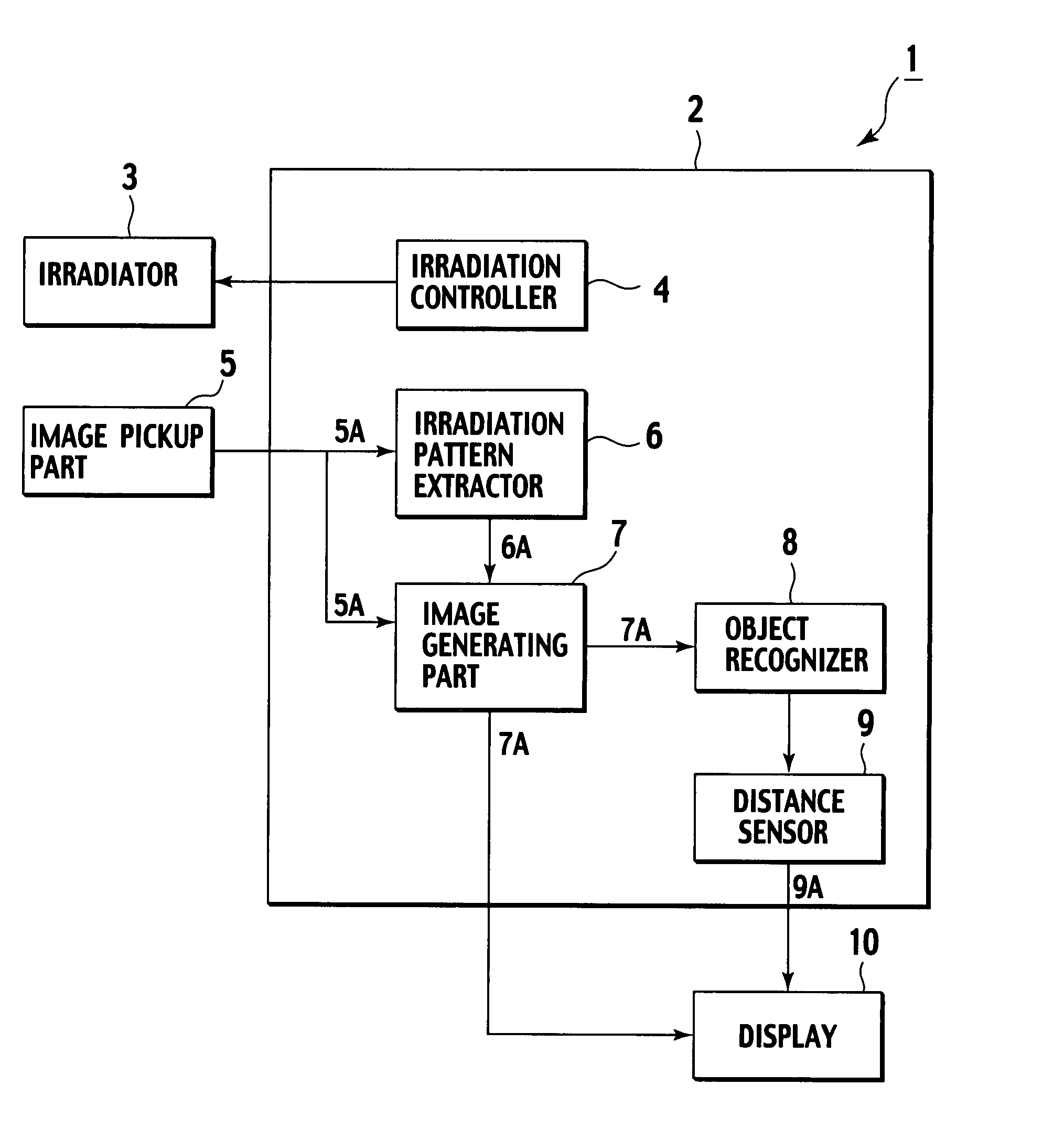
[0026]A block diagram of the image processor is to be explained referring to FIG. 1, according to a first embodiment of the present invention.
[General Structure of Image Processor 1]
[0027]As shown in FIG. 1, an image processor 1 according to the first embodiment of the present invention mainly includes an irradiator 3, an irradiation controller 4, an image pickup part 5, an irradiation pattern extractor 6, an image generating part 7, an object recognizer 8, a distance sensor 9, a display 10, and an administrative processor 2. The administrative processor 2 administratively controls each of the above elements of the image processor 1.
[Details of Each Structural Element]
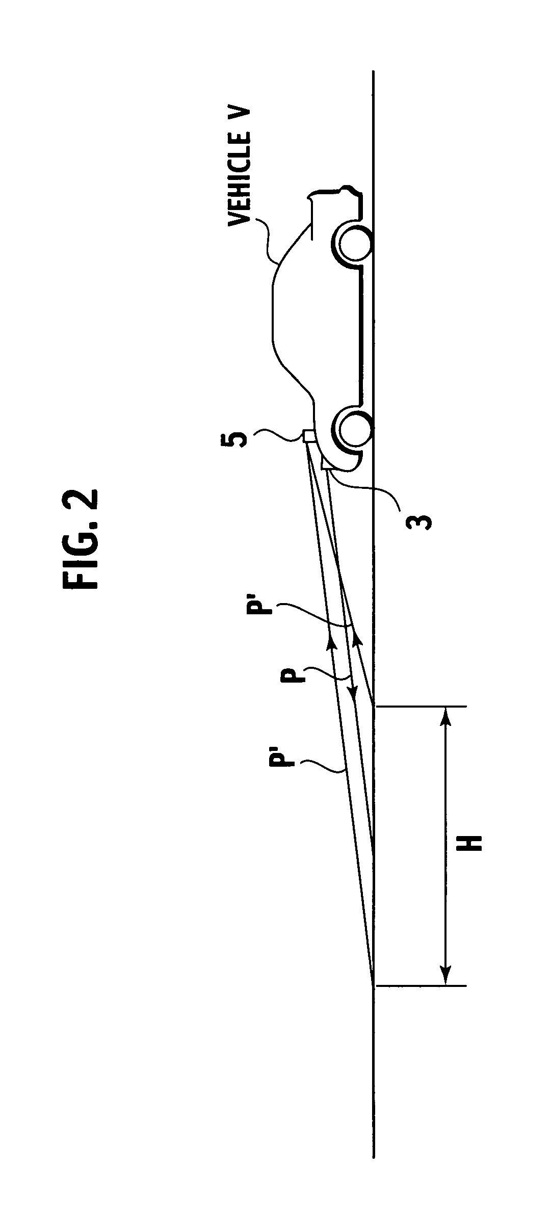
[0028]To an image pickup area H picked up by the image pickup part 5, the irradiator 3 sends an irradiation pattern P necessary for sensing a distance D between an object 15 and a vehicle V, as shown in FIG. 2. Herein, wavelength of an irradiated light is not especially limited, therefore a visible light or an infrared...
second embodiment
[0052]Then, a block diagram of the image processor 1 is to be explained referring to FIG. 6, according to a second embodiment of the present invention. Herein, explanations about structural elements like those of the image processor 1 according to the first embodiment are to be omitted, therefore different structural elements only are to be explained.
[General Structure of Image Processor 1]
[0053]As shown in FIG. 6, the image processor 1 according to the second embodiment of the present invention mainly includes the irradiator 3, the irradiation controller 4, the image pickup part 5, the irradiation pattern extractor 6, the image generating part 7, the object recognizer 8, the distance sensor 9, the display 10, a frequency analyzer 11, and the administrative processor 2. The administrative processor 2 administratively controls each of the above elements of the image processor 1.
[Details of Each Structural Element]
[0054]The irradiation pattern extractor 6 according to the first embodi...
third embodiment
[0060]Then, a block diagram of the image processor 1 is to be explained referring to FIG. 7, according to a third embodiment of the present invention. Herein, explanations about structural elements like those of the image processor 1 according to the first and second embodiments are to be omitted, therefore different structural elements only are to be explained.
[General Structure of Image Processor 1]
[0061]As shown in FIG. 7, the image processor 1 according to the third embodiment of the present invention mainly includes the irradiator 3, the irradiation controller 4, the image pickup part 5, the irradiation pattern extractor 6, the image generating part 7, the object recognizer 8, the distance sensor 9, the display 10, a luminance determiner 12, and the administrative processor 2. The administrative processor 2 administratively controls each of the above elements of the image processor 1.
[Details of Each Structural Element]
[0062]The luminance determiner 12 determines whether a per-...
PUM
 Abstract
Description
Claims
Application Information
 - R&D
- Intellectual Property
- Life Sciences
- Materials
- Tech Scout
- Unparalleled Data Quality
- Higher Quality Content
- 60% Fewer Hallucinations
Browse by: Latest US Patents, China's latest patents, Technical Efficacy Thesaurus, Application Domain, Technology Topic, Popular Technical Reports.
© 2025 PatSnap. All rights reserved.Legal|Privacy policy|Modern Slavery Act Transparency Statement|Sitemap|About US| Contact US: help@patsnap.com