Quick-release annuloplasty ring holder

a technology of annuloplasty ring and ring holder, which is applied in the field of holder for annuloplasty ring and mitral annuloplasty ring, can solve the problems of valve malfunction, leaflet flailing, and chordae tendineae (the chords) being stretched, and achieves the effect of facilitating the cutting of the template from the ring

Active Publication Date: 2012-04-10
EDWARDS LIFESCIENCES CORP
View PDF89 Cites 167 Cited by
  • Summary
  • Abstract
  • Description
  • Claims
  • Application Information

AI Technical Summary

Benefits of technology

[0035]The present invention provides an annuloplasty ring and holder assembly, comprising an annuloplasty ring including a suture-permeable outer cover and a template. The template has an upper, proximal face and a lower, distal face and a peripheral edge sized and adapted to receive the annuloplasty ring in conformal contact therewith. The template further includes a single cutting well adjacent the peripheral edge defined by a pair of spaced apart walls extending upward from the proximal face, and two spaced cleats adjacent the template peripheral edge each positioned at least 90° circumferentially around the peripheral edge from the cutting well. A flexible connecting filament has its free ends anchored to the two spaced cleats and a mid-portion passing through at least two points on the annuloplasty ring outer cover and emerging above the proximal face of the template at only one location where it is suspended across the cutting well. In this way, the task of severing the template from the ring is rendered extremely easy.

Problems solved by technology

Valve malfunction can result from the chordae tendineae (the chords) becoming stretched, and in some cases tearing.
When a chord tears, the result is a leaflet that flails.
Also, a normally structured valve may not function properly because of an enlargement of or shape change in the valve annulus.
This condition is referred to as a dilation of the annulus and generally results from heart muscle failure.
In addition, the valve may be defective at birth or because of an acquired disease.
As a result, an undesired back flow of blood from the left ventricle into the left atrium can occur.
First, blood flowing back into the atrium may cause high atrial pressure and reduce the flow of blood into the left atrium from the lungs.
As blood backs up into the pulmonary system, fluid leaks into the lungs and causes pulmonary edema.
Second, the blood volume going to the atrium reduces volume of blood going forward into the aorta causing low cardiac output.
Excess blood in the atrium over-fills the ventricle during each cardiac cycle and causes volume overload in the left ventricle.
Organic mitral regurgitation results from a structurally abnormal valve component that causes a valve leaflet to leak during systole.
Functional mitral regurgitation is a significantly aggravating problem for the dilated heart, as is reflected in the increased mortality of these patients compared to otherwise comparable patients without functional mitral regurgitation.
The problem with surgical therapy is the significant insult it imposes on these chronically ill patients with high morbidity and mortality rates associated with surgical repair.
This is because, in organic mitral regurgitation, the problem is not the annulus but in the central valve components.
After surgery, the repaired valve may progress to high rates of functional mitral regurgitation over time.
Flexible rings are indicated for certain conditions, but do not perform a remodeling annuloplasty given their inherent lack of rigidity.
Such rings would not be suitable for correcting a mitral valve deficiency.
Because of the presence of multiple implant and connecting sutures in the surgical fields, the step of disconnecting the ring from the holder with a scalpel is somewhat delicate, and can be confusing for the novice.

Method used


Image

  • Quick-release annuloplasty ring holder
  • Quick-release annuloplasty ring holder
  • Quick-release annuloplasty ring holder

Examples


Embodiment Construction

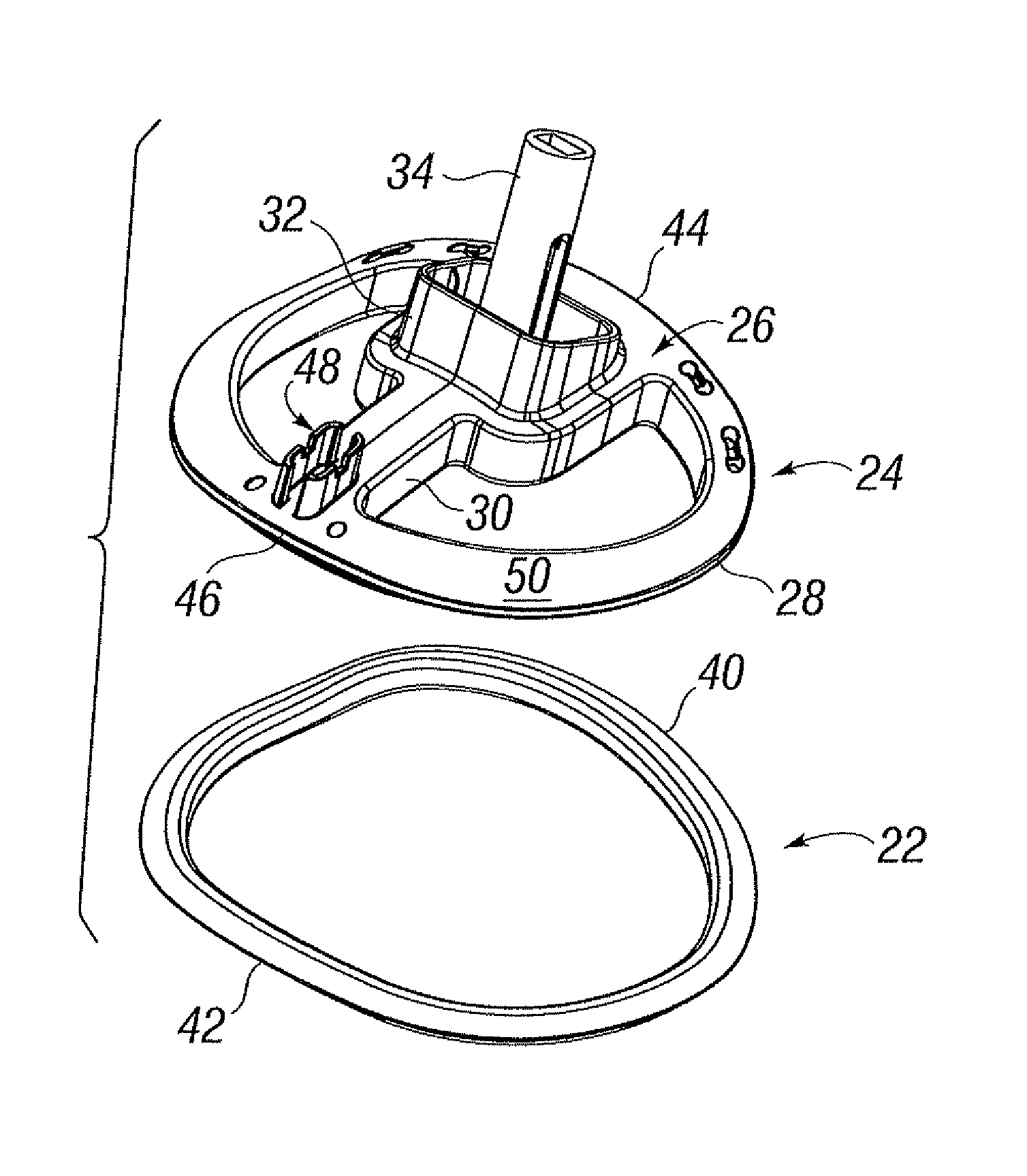
[0064]The present invention provides an annuloplasty ring holder that facilitates an implant procedure. In particular, the holder of the present invention provides a quick-release cutting structure for severing connecting filaments between the holder and the annuloplasty ring. The surgeon need only to cut the connecting filaments at a single point. Moreover, the single cutting point is highly visible and located away from interfering structure on the holder.

[0065]The holder accommodates annuloplasty ring that are open or discontinuous (e.g., C-shaped) or closed or continuous (e.g., D-shaped). The ring can be rigid, flexible, or semi-flexible. The holders of the present invention can conform to planar or nonplanar rings, and are adaptable to rings used to repair any of the annuluses within the heart. Indeed, the holders of the present invention can even be utilized to hold heart valves, thus providing a quick release structure to separate the holder from the valve.

[0066]That said, th...


PUM


Abstract

A holder for an annuloplasty ring having a template defining a proximal face opposite the distal face, and a peripheral edge about which the annuloplasty ring conforms. The annuloplasty ring anchors to the template using one or more flexible filaments. The template includes a single cutting well on its proximal face over which the flexible filament is suspended. Desirably, the single cutting well is located adjacent the peripheral edge so as to be away from any handle connections for ease of access. The flexible filament emerges above the proximal face of the template at only one location at the cutting well, thus presenting a one cut quick-release structure that is highly visible to the surgeon. The annuloplasty ring may have a relatively rigid inner core surrounded by a suture-permeable cover, and the peripheral edge may be formed by a lower axial wall and an upper radial ledge that projects outward from the rigid inner core but not quite as far as a sewing margin of the ring. The ring and holder may be for mitral annuloplasty rings and generally have a D shape in plan view, and may be three-dimensional with upward anterior and posterior bows.

Description

CROSS-REFERENCE TO RELATED APPLICATION[0001]The present application claims priority to U.S. Provisional Application No. 61 / 052,016, filed May 9, 2008, which is incorporated herein by reference.FIELD OF THE INVENTION[0002]The present invention relates generally to holders for medical implants, and particularly to a holder for an annuloplasty ring, especially a mitral annuloplasty ring.BACKGROUND OF THE INVENTION[0003]In vertebrate animals, the heart is a hollow muscular organ having four pumping chambers as seen in FIG. 1: the left and right atria and the left and right ventricles, each provided with its own one-way valve. The natural heart valves are identified as the aortic, mitral (or bicuspid), tricuspid and pulmonary, and are each mounted in an annulus comprising dense fibrous rings attached either directly or indirectly to the atrial and ventricular muscle fibers. Each annulus defines a flow orifice.[0004]The atriums are the blood-receiving chambers, which pump blood into the v...

Claims


Application Information

Patent Timeline
Patent Type & Authority Patents(United States)
IPC IPC(8): A61F2/24
CPCA61F2/2466A61F2/2448A61F2/2412A61F2/2427
Inventor RAO, ANAND R.FANN, HILDA Z.
Owner EDWARDS LIFESCIENCES CORP
Why Eureka
Try Eureka