Dynamic compression device and driving tool

a technology of dynamic compression and driving tool, which is applied in the field of fasteners, can solve the problems of early mechanical failure, damage to the spring section shown in these patents, and mechanical failure of springs, so as to reduce the bending moment, reduce bone ingrowth, and facilitate the task of removing the screw

Inactive Publication Date: 2007-02-13
BOARD OF RGT UNIV OF NEBRASKA
View PDF29 Cites 112 Cited by
  • Summary
  • Abstract
  • Description
  • Claims
  • Application Information

AI Technical Summary

Benefits of technology

[0008]The screw of this invention has an enlarged head in the preferred embodiment, the head having a flange that is partially spherical. A washer fits between the flange and the bone surface, and has one side for engaging the bone exterior. The interior of the washer comprises a mating spherical surface for engaging the flange of the head. The spherical surface allows the axis of the washer to incline relative to the axis of the screw.
[0009]A stabilizing pin preferably fits within the cavity of the screw after the tool has been removed. The stabilizing pin extends through the spring section, reducing bending moments and protecting the spring. Also, the stabilizing pin retards bone ingrowth into the cavity. Reducing bone ingrowth makes the task of removing the screw easier if the screw is later removed.

Problems solved by technology

The spring sections shown in these patents, however, could be damaged during insertion because the torque applied to the head of the screw passes through the spring section.
This torque would result in torsional deformation of the spring section during insertion, which could create stress risers within the spring that could lead to early mechanical failure.
Furthermore, during the process of removal, the spring could distort and fail mechanically, requiring extraction methods that could be more destructive to the bone.

Method used


Image

  • Dynamic compression device and driving tool
  • Dynamic compression device and driving tool
  • Dynamic compression device and driving tool

Examples


Embodiment Construction

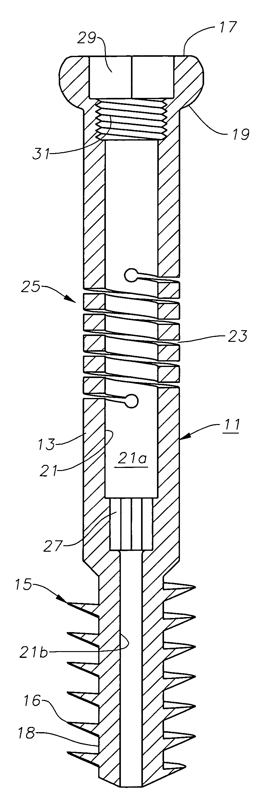
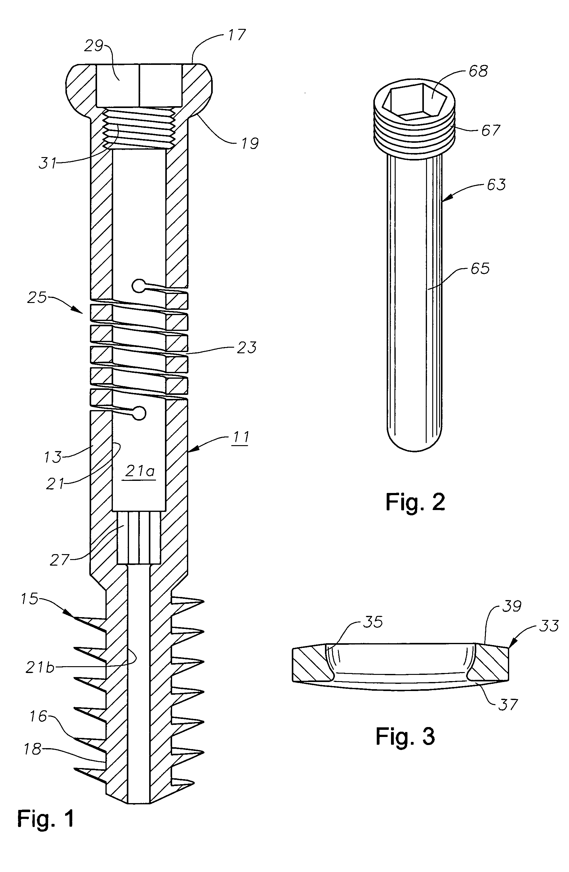
[0019]Referring to FIG. 1, the fastener of this invention includes comprises a screw 11 in the preferred embodiment that has an elongated body 13. Screw 11 may be formed of various biocompatible materials such as stainless steel or vitallium, but preferably is formed of titanium or titanium alloy because of the enhanced fatigue properties.

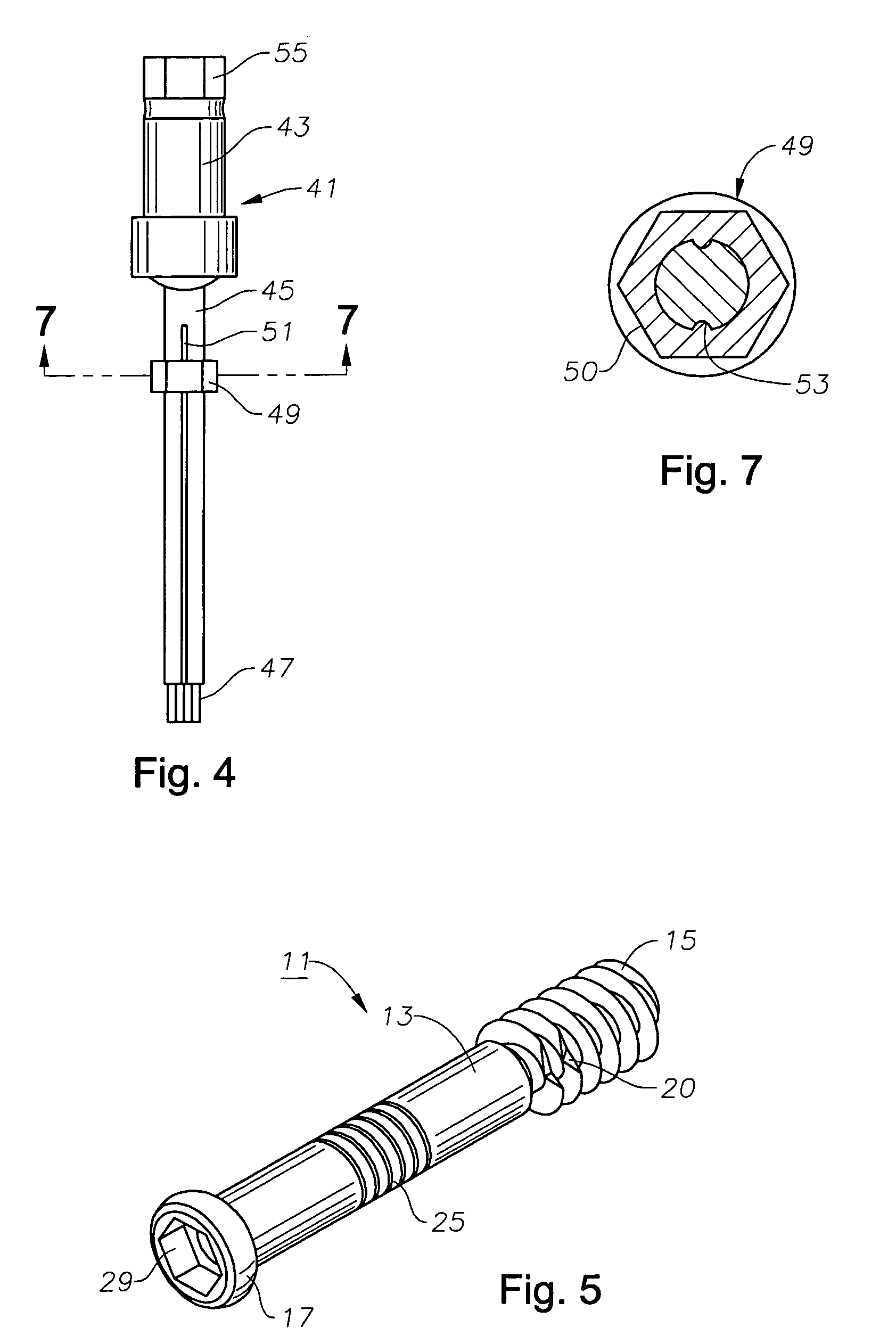
[0020]Screw body 13 has an anchor section on its distal end, which preferably comprises a set of external threads 15. Threads 15 may be a variety of types, but are shown as having a saw-tooth configuration with a sharp crest 16. A cylindrical root 18 locates between adjacent crests 16. The outer diameter of threads 15 measured at crests 16 is uniform, except for the first thread 15 at the distal end, which is slightly smaller. The outer diameter of threads 15 is larger than the outer diameter of body 13. Threads 16 have a low pitch, a considerable dimension from root 18 to crest 16, and resemble a flight of an auger. As shown in FIG. 5, one or two ...


PUM


Abstract

A bone screw has a spring section to allow the screw to elongate while it is being installed. The screw has a cavity with a proximal drive surface and a distal drive surface. The drive surfaces are located on opposite sides of the spring section. A drive tool that has proximal and distal drive members fits within the cavity. Rotating the drive tool transmits torque to both the proximal and distal drive sockets simultaneously.

Description

FIELD OF THE INVENTION[0001]This invention relates in general to fasteners for fastening portions of a fractured bone together.BACKGROUND OF THE INVENTION[0002]One method of bone fracture repair comprises securing screws across the fractured portions of the bone. The purpose of the screw or screws is to tightly secure the bone fragments together while the bone heals. Typically, the screws comprise lag design, each being a solid member having an externally threaded section on one end and a head on the other end. The head bears against the exterior surface of the bone when the screw is secured to a desired torque to place the bone fragments in compression.[0003]During the process of revascularization, the edges of the fracture commonly will resorb, typically about 1 to 3 mm. This movement reduces or eliminates the initial compression that the screw has provided. A bone lag screw that could provide continuous dynamic compression across the fracture while accommodating resorption as the...

Claims


Application Information

Patent Timeline
Patent Type & Authority Patents(United States)
IPC IPC(8): A61B17/56A61F2/30A61B17/72A61B17/86A61B17/88
CPCA61B17/7225A61B17/8625A61B17/888A61B17/8875A61B17/8695A61B17/864
Inventor NEFF, JAMES R.
Owner BOARD OF RGT UNIV OF NEBRASKA
Why Eureka
Try Eureka