Method, apparatus and system for encoding and decoding broadband voice signal

a broadband voice signal and encoding technology, applied in the field of encoding and decoding broadband voice signals, can solve the problems of inability to solve long-term solutions to techniques, poor quality of packets, and distorted time-varying characteristics, and achieve the effects of supporting the signal-to-noise ratio (snr), reducing quantization errors, and good performan

Inactive Publication Date: 2012-09-18
SAMSUNG ELECTRONICS CO LTD +1
View PDF22 Cites 4 Cited by
  • Summary
  • Abstract
  • Description
  • Claims
  • Application Information

AI Technical Summary

Benefits of technology

[0011]Exemplary embodiments of the present invention provide a method and apparatus for encoding a broadband voice signal and supporting Signal-to-Noise Ratio (SNR) expendability with good performance by improving an existing sinusoidal model and reducing a quantization error in order to encode the broadband voice signal.
[0012]According to an aspect of the present invention, there is provided a method of encoding and decoding a broadband voice signal, the method comprising extracting a linear prediction coefficient (LPC) from the broadband voice signal; outputting a linear prediction (LP) residual signal obtained by removing an envelope from the broadband voice signal using the LPC; pitch-searching a spectrum of the LP residual signal; extracting spectral magnitudes and phases of the LP residual signal, the spectral magnitudes and phases corresponding to a damping factor, by adding the damping factor to a matching pursuit algorithm; obtaining a first spectral magnitude and a first phase, at which a power value of the LP residual signal is minimized, from among the extracted spectral magnitudes and phases; quantizing the first spectral magnitude and the first phase; and decoding the broadband voice signal.
[0019]A method of quantizing the first phase may comprise obtaining distances by obtaining differences between the first phase and first codebook phases generated from the first phase, multiplying the differences by an envelope value corresponding to the first phase, and adding each of the differences to the respective multiplication results; detecting and outputting a first codebook phase allowing the distance to be minimized; generating a second phase by adjusting a phase error vector generated from a difference between the first codebook phase and the first phase, and obtaining distances by obtaining differences between the second phase and second codebook phases generated from the second phase, multiplying the differences by an envelope value corresponding to the second phase, and adding the differences to the respective multiplication results; and detecting and outputting a second codebook phase allowing the distance to be minimized.

Problems solved by technology

However, the packet switching method may cause channel congestion, resulting in packet loss and inferior sound quality.
Although a technique of hiding a damaged packet may be used in order to address these problems, this technique is not a long term solution to these problems.
Due to this assumption, when a voice signal having a time varying characteristic is synthesized by a decoder end, the time varying characteristic is distorted, and discontinuity between frames occurs.
However, the parameter interpolation method or the waveform interpolation method causes modification of a voice waveform, resulting in distortion of a waveform during a non-stationary period.
In particular, a significant decrease in sound quality occurs due to distortion of a waveform in the voice signal in an onset or offset transition duration.
However, the related art harmonic coding method has the limitation that a frequency resolution of less than 512 points must be applied due to restrictions of complexity and on data rate.
A decrease of the frequency resolution and a transmission restriction of a phase parameter obstruct correct harmonic peak detection, and as a result, the performance of a voice encoder decreases due to delays in pulse positions of a synthesized voice signal and phase differences between frames.

Method used


Image

  • Method, apparatus and system for encoding and decoding broadband voice signal
  • Method, apparatus and system for encoding and decoding broadband voice signal
  • Method, apparatus and system for encoding and decoding broadband voice signal

Examples


Embodiment Construction

[0032]The attached drawings for illustrating exemplary embodiments of the present invention are referred to in order to gain a sufficient understanding of the present invention, the merits thereof, and the objectives accomplished by the implementation of the present inventive concept.

[0033]Hereinafter, the present inventive concept will be described in detail by explaining exemplary embodiments of the invention with reference to the attached drawings. In the drawings, like reference numerals in the drawings denote like elements.

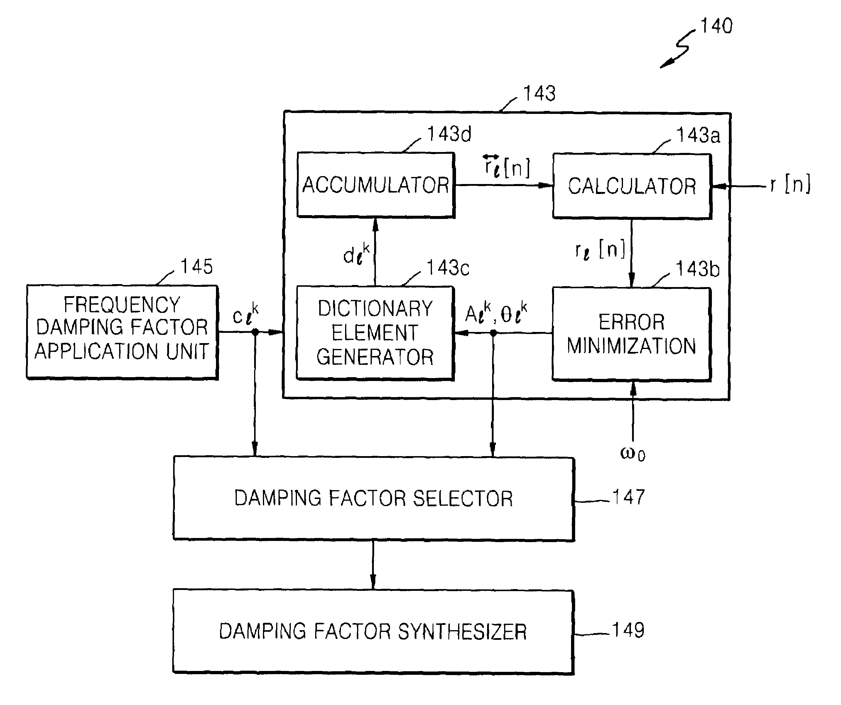
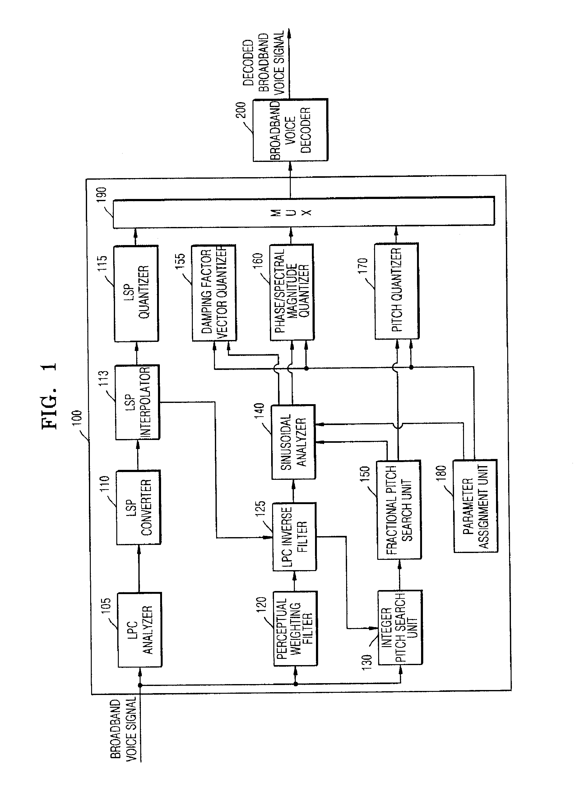
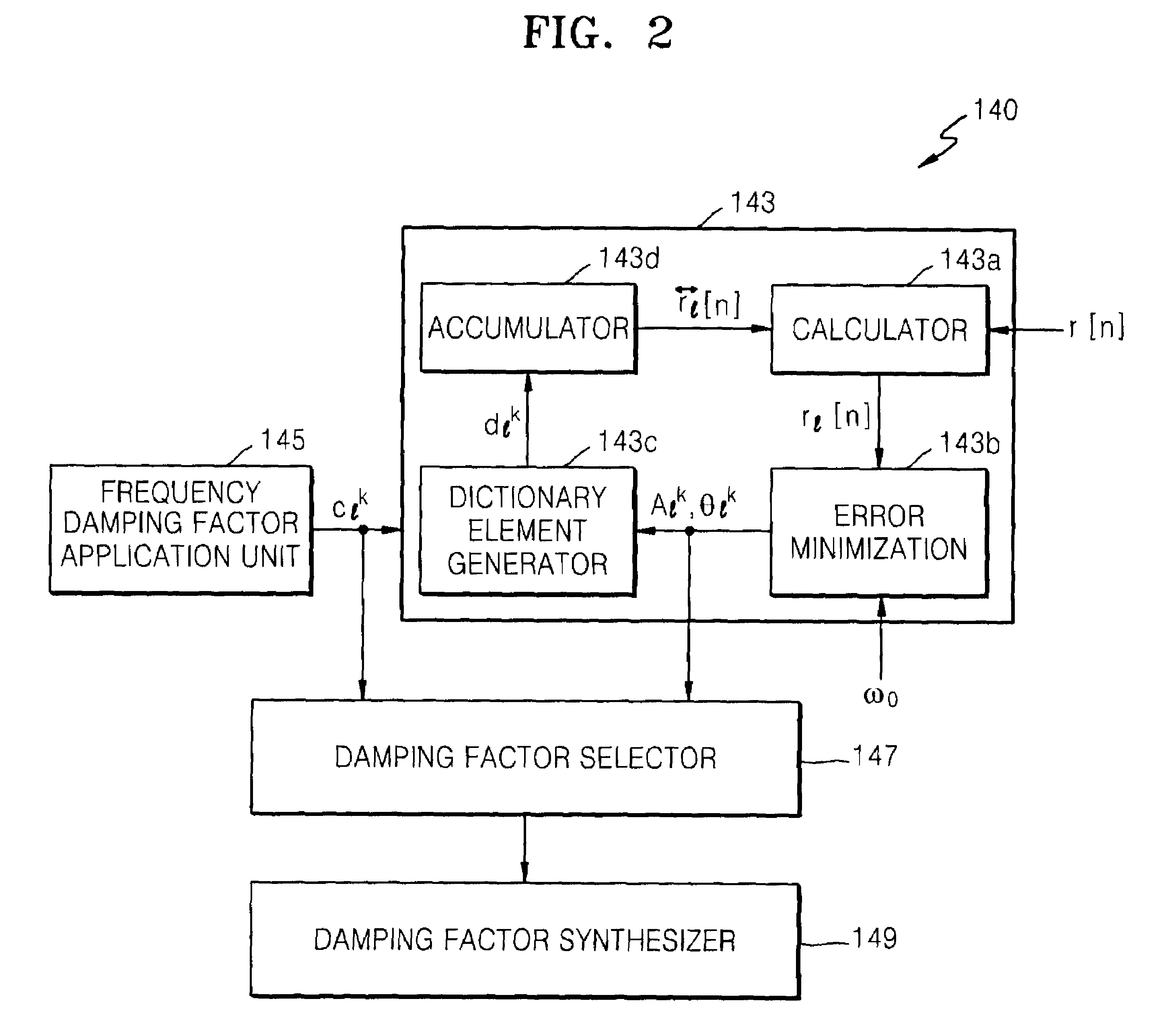
[0034]FIG. 1 is a block diagram of a broadband voice signal encoding and decoding system according to an exemplary embodiment of the present invention.

[0035]Referring to FIG. 1, the broadband voice encoding and decoding system includes a broadband voice encoder 100 and a broadband voice decoder 200.

[0036]The broadband voice encoder 100 includes a Linear Prediction Coefficient (LPC) analyzer 105, a Line Spectral Pairs (LSP) converter 110, an LSP interpolator 1...


PUM


Abstract

A method, apparatus, and system for encoding or decoding a broadband voice signal are provided. The method includes extracting a linear prediction coefficient (LPC) from the broadband voice signal; outputting a linear prediction (LP) residual signal; pitch-searching a spectrum of the LP residual signal; extracting spectral magnitudes and phases of the LP residual signal, which correspond to a damping factor; obtaining, from among the extracted spectral magnitudes and phases, a first spectral magnitude and a first phase at which a power value of the LP residual signal is minimized; quantizing the first spectral magnitude and the first phase; and decoding the broadband voice signal. The apparatus includes a linear prediction coefficient (LPC) analyzer; an LPC inverse filter; a pitch searching unit; a sinusoidal analyzer; and a phase and spectral magnitude quantizer. The system includes a broadband voice encoding apparatus and a broadband voice decoding apparatus.

Description

CROSS-REFERENCE TO RELATED PATENT APPLICATION[0001]This application claims priority from Korean Patent Application No. 10-2006-0118546, filed on Nov. 28, 2006, in the Korean Intellectual Property Office, the disclosure of which is incorporated herein in its entirety by reference.BACKGROUND OF THE INVENTION[0002]1. Field of the Invention[0003]Methods, apparatuses, and systems consistent with the present invention relate to encoding and decoding a broadband voice signal, and more particularly, to encoding and decoding a broadband voice signal using a matching pursuit sinusoidal model to which a damping factor is added.[0004]2. Description of the Related Art[0005]The variety of application fields of voice communication and an increase in the data transmission rates of networks have resulted in an increase in the demand for high-quality voice communication. In order to meet the need for high-quality voice communication, a broadband voice signal having 50-7000 Hz bandwidth needs to be tr...

Claims


Application Information

Patent Timeline
Patent Type & Authority Patents(United States)
IPC IPC(8): G10L19/02G10L19/00G10L19/08G10L19/09
CPCG10L19/09G10L19/04G10L19/12
Inventor LEE, IN-SUNGKIM, JONG-HARKJEONG, GYU-HYEOKSEO, SANG-WON
Owner SAMSUNG ELECTRONICS CO LTD
Why Eureka
Try Eureka