Air guiding device

a technology of air guiding and guiding device, which is applied in the direction of roofs, transportation and packaging, vehicle arrangements, etc., can solve the problems of increasing the vacuum on the side of the front, already being aerodynamically effective, etc., and achieves the effect of reducing both air resistance and lifting on the vehicl

Active Publication Date: 2012-10-30
DR ING H C F PORSCHE AG
View PDF27 Cites 47 Cited by
  • Summary
  • Abstract
  • Description
  • Claims
  • Application Information

AI Technical Summary

Benefits of technology

[0007]The invention relates to an air guiding device on an undersurface or on a front end part that reduces both air resistance and also lift on the vehicle. The air guiding device has an air guiding body automatically changes shape and adjusts as the speed of travel increases. More particularly, the air guiding body comprises an elongate attachment that extends in the longitudinal direction of the vehicle and comprises a flexible material. The air guiding body has a cross section in the form of a half shell with a lateral opening between the undersurface and the inner lateral edge of the air guiding body. The air guiding body can be adjusted automatically in the driving condition from a rest position into an operative position, in which it can be lowered in the direction of the roadway. In the rest position, the air guiding body has a bulging shape that arches continuously down and, in the lowered operative position, the air guiding body can be adjusted to a bulging shape that arches down continuously to a greater extent.
[0009]The air guiding device is in the rest position or shape when the vehicle is traveling slowly and is hardly visible, if at all, in this rest position. However, the air guiding device already is aerodynamically effective when the vehicle is traveling slowly. As the speed of travel increases, the air flowing outward from the center of the vehicle at the undersurface leads to an increasing vacuum on the side of the front wheels remote from the vehicle wheel. The resulting forces deform the air guiding device in a way that improves the aerodynamic effectiveness as the speed of travel increases. The air guiding device forms a bulging air guiding body in its optimum operative shape at high speed. More particularly, an air guiding body that is arched convexly down on the side remote from the vehicle wheel directs the air flow away from the vehicle wheel and thereby allowing a reduction both in air resistance and the lift of the vehicle. If the speed of travel is reduced again, the shape of the air guiding body changes back to the initial condition or rest condition by virtue of elastic restoring forces.
[0011]A rear end edge of the air guiding body preferably has an elastic fastening tab in the form of a u-shaped hook that can be hooked into slots in the undersurface. The hook allows deformation of the air guiding body into the operative position and is designed to produce restoring forces. The flexible attachment of the air guiding body by means of the individual tabs and by means of the elastic hook-shaped fastening tab allows deformation or adjustment of the air guiding body, and it is possible to produce restoring forces that return the air guiding body from the operative position to the rest position.
[0013]Two identical air guiding bodies preferably are arranged ahead of each vehicle wheel with the lateral openings of the air guiding bodies in the form of half shells lying opposite one another. The air guiding bodies preferably are parallel to one another and are separated by an interspace. One air guiding body preferably is close to the outside of the vehicle and the other air guiding body preferably is ahead of and as an extension of an inner wheel arch wall. An optimum aerodynamic effect is achieved since one air guiding body is as close as possible to the outer flank of the wheel, i.e. as far as possible at the outside of the bottom part of the front end. This effect can be enhanced further if the outer wheel flank facing the center of the vehicle also is covered by an air guiding body arranged in mirror-image fashion.
[0015]The air guiding bodies guide incident air around the vehicle wheels, preferably around the front wheels. This air guiding effect is achieved through the change in the shape of the air guiding body with increasing speed of travel due to forces acting at the undersurface, and the aerodynamic properties of the vehicle thus are improved. Moreover, there is no negative effect on either the appearance or ground clearance of the vehicle with the two air guiding bodies or the single air guiding body in the rest position.

Problems solved by technology

However, the air guiding device already is aerodynamically effective when the vehicle is traveling slowly.
As the speed of travel increases, the air flowing outward from the center of the vehicle at the undersurface leads to an increasing vacuum on the side of the front wheels remote from the vehicle wheel.

Method used


Image

  • Air guiding device
  • Air guiding device
  • Air guiding device

Examples


Embodiment Construction

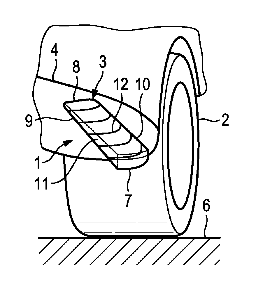
[0027]An air guiding device 1, 1a on a vehicle is arranged in an area ahead of a vehicle wheel, preferably ahead of a front wheel 2. The air guiding device 1, 1a comprises an air guiding body 3 attached to an undersurface 4 of a wheel arch or to a front end part 5 and projects in the direction of a roadway 6.

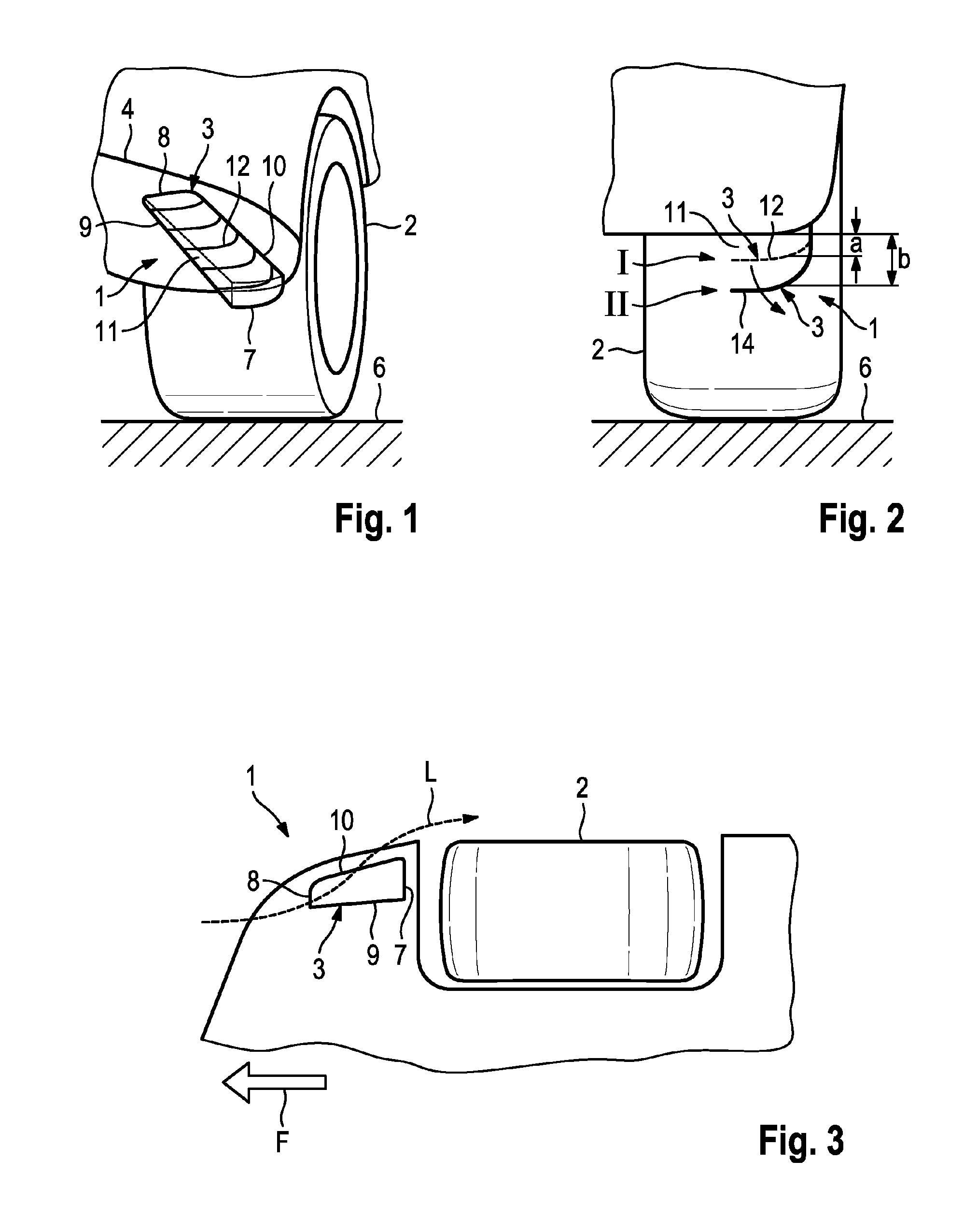
[0028]The air guiding body 3 is an elongate attachment extending in the longitudinal direction of the vehicle and is made of a flexible or soft-elastic material that allows a change in shape and adjustment of the air guiding body 3. The air guiding body 3 is in the form of a half shell and, in the driving condition, can be adjusted automatically from a rest position I into a lowered, operative position II, as shown schematically by FIG. 2.

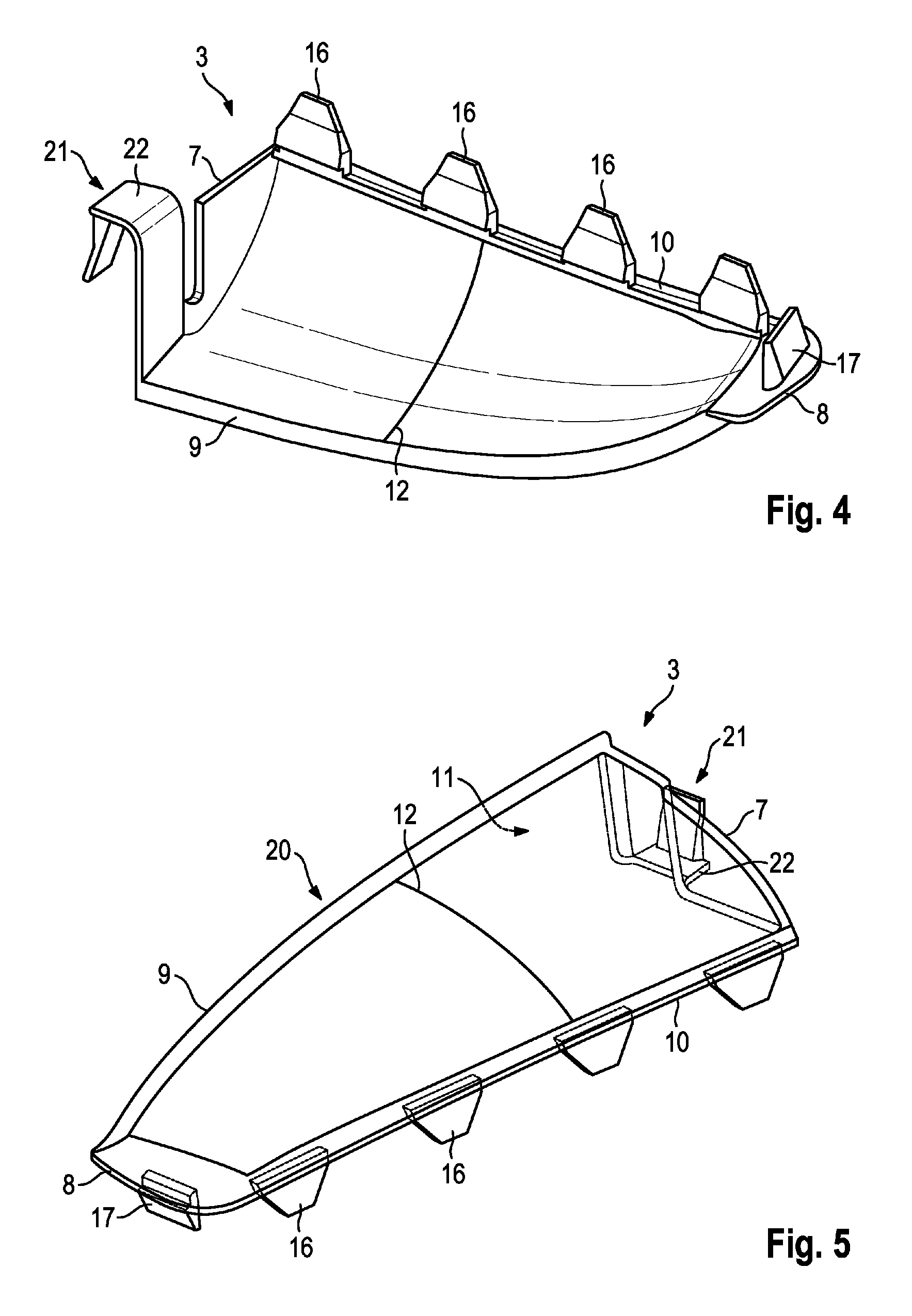
[0029]The air guiding body 3 is tapered in a wedge shape to become narrower from a rear end 7 to a front end 8. An inner lateral edge 9 extends in a shallow arc, and the opposite lateral edge 10, which is situated on the outside, has a rectilin...


PUM


Abstract

The air guiding device has one or more air guiding bodies. Each air guiding body has an elongate attachment that extends in the longitudinal direction of the vehicle that bulges in a convex manner, is composed of a flexible or soft-elastic material and is embodied in the form of a half shell having a lateral elongate opening and can be adjusted automatically in the driving condition from a rest position into an operative position, in which it can be lowered in the direction of the roadway. In the rest position, the air guiding body is arranged close to the undersurface and, in the operative position, the air guiding body is held in a lowered position relative to the undersurface.

Description

CROSS REFERENCE TO RELATED APPLICATION[0001]This application claims priority under 35 USC 119 to German Patent Application No 10 2010 036 442.8 filed on Jul. 16, 2010, the entire disclosure of which is incorporated herein by reference.BACKGROUND OF THE INVENTION[0002]1. Field of the Invention[0003]The invention relates to an air guiding device.[0004]2. Description of the Related Art[0005]EP 2 039 595 A1 discloses an air guiding device for a vehicle with a wheel spoiler arranged in the area ahead of a vehicle wheel and projecting down in the direction of the roadway from the undersurface area of the vehicle. The air guiding device has a guide fin that adjoins the wheel spoiler and extends in a vertical plane approximately parallel to the direction of travel. An air flow is channeled in the areas of the wheels and the wheel arch.[0006]It is the object of the invention to provide an air guiding device ahead of the wheels of a vehicle by means of which the aerodynamic properties of the ...

Claims


Application Information

Patent Timeline
Patent Type & Authority Patents(United States)
IPC IPC(8): B62D63/02
CPCB62D35/005B62D35/02Y02T10/88Y02T10/82
Inventor WOLF, THOMASPENTIA, BOGDANLEMKE, TIMO
Owner DR ING H C F PORSCHE AG
Why Eureka
Try Eureka