Automated banking machine system and monitoring method

Inactive Publication Date: 2012-11-06
SECURITAS ELECTRONICS SECURITY INC
View PDF8 Cites 12 Cited by
  • Summary
  • Abstract
  • Description
  • Claims
  • Application Information

AI Technical Summary

Problems solved by technology

For example if in the course of capturing image data, a camera adjacent to the ATM is unable to produce usable video, such as because it i

Method used


Image

  • Automated banking machine system and monitoring method
  • Automated banking machine system and monitoring method
  • Automated banking machine system and monitoring method

Examples


Example

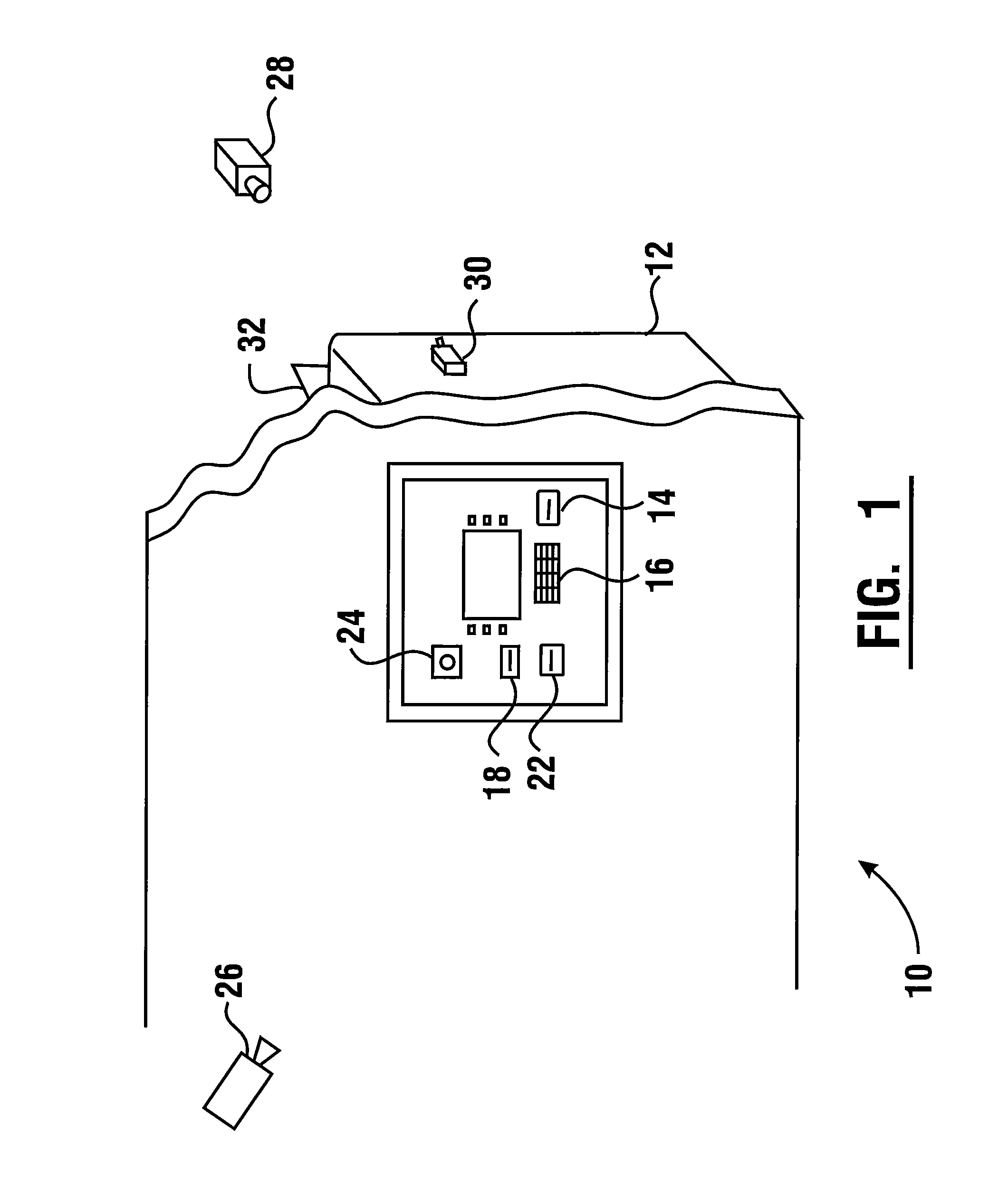
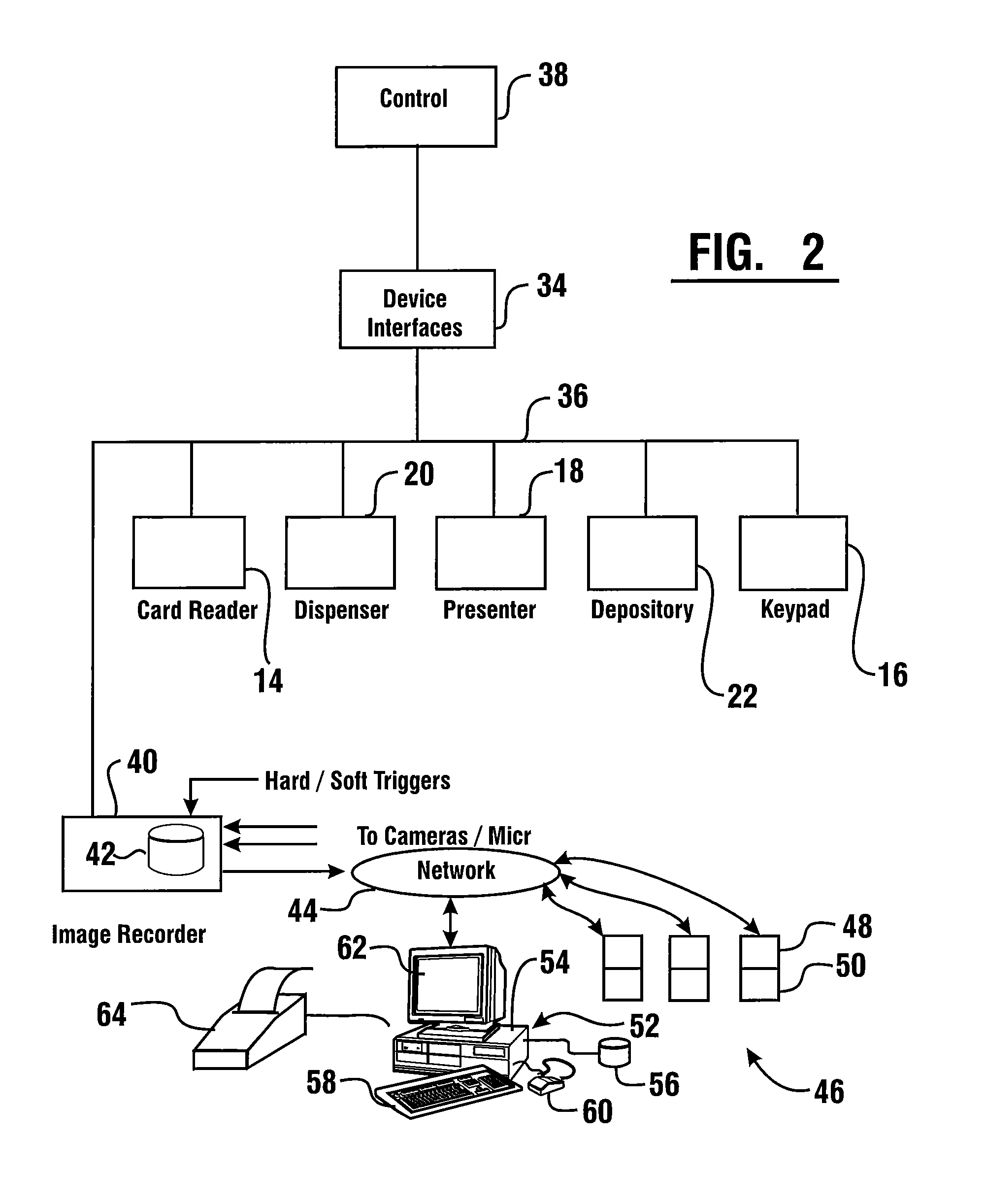
[0124]Referring now to the drawings and particularly to FIG. 1 there is shown therein an exemplary embodiment which operates as a transaction record system for an automated banking machine generally indicated 10. The system of this embodiment includes an automated banking machine 12 which in this example is an ATM. It should be understood that in other embodiments other types of automated banking machines may be used. ATM 12 includes a number of transaction function devices. These transaction function devices are associated with components of the machine such as a card reader 14 and a keypad 16. The card reader and keypad serve as input devices through which users can input instructions and information. It should be understood that as referred to herein the keypad includes function keys or touch screen inputs which may be used in other embodiments to input data into the machine.

[0125]ATM 12 further includes additional transaction function devices. Such transaction function devices m...


PUM


Abstract

An automated banking machine is part of a banking system that can cause financial transfers responsive to data read from data bearing records, including user cards. The machine is in operative connection with a system operable to capture images related to activity that is conducted at or adjacent to the machine. The machine is positioned at a banking facility having a vault and an entrance. A plurality of cameras are positioned at the facility. Captured images can be analyzed at a remote monitoring center. The monitoring center can operate to assure that employees or customers of the banking facility can safely enter and/or exit the banking facility.

Description

CROSS REFERENCE TO RELATED APPLICATIONS[0001]This application is a continuation of 13 / 068,592 filed May 16, 2011, which is a continuation of Ser. No. 11 / 825,553 filed Jul. 6, 2007, now U.S. Pat. No. 7,942,313, which claims benefit pursuant to 35 U.S.C. §119(e) of provisional applications 60 / 819,696, 60 / 819,698, and 60 / 819,699 filed Jul. 7, 2006. The disclosure of each of these applications is herein incorporated by reference.TECHNICAL FIELD[0002]This invention relates to transaction systems. Specifically exemplary embodiments relate to a system for an automated banking machine that is actuated by user cards and which provides image records as well as data records related to transactions and other activities. Exemplary embodiments further relate to a system which captures images and enables images and data to be stored, remotely accessed and selectively processed and analyzed. Exemplary embodiments further relate to systems that monitor facilities and individuals.BACKGROUND OF INVENT...

Claims


Application Information

Patent Timeline
IPC IPC(8): G06Q40/00G07D11/00G07F19/00
CPCG06Q40/02G07F19/207
Inventor GRIMM, JACQUELINEJONES, MIKEDAVISSON, DANEENRIGHT, JEFFERY M.
Owner SECURITAS ELECTRONICS SECURITY INC
Why Eureka
Try Eureka