Coaxial connector

a technology of coaxial connectors and coaxial cables, applied in the direction of coupling devices, two-part coupling devices, electrical apparatus, etc., can solve the problems of manual work, high frequency and magnitude of power used for this purpose, complicated work and management, and preferable in view of safety, reliability, and time saving, so as to improve work efficiency, work easier and simpler, and reduce manual work errors

Active Publication Date: 2012-12-04
GV TECH
View PDF1 Cites 4 Cited by
  • Summary
  • Abstract
  • Description
  • Claims
  • Application Information

AI Technical Summary

Benefits of technology

[0011]The invention has been made in view of the circumstances described above, and an object thereof is to provide a technique to connect connectors that electrically connect coaxial cables, in particular coaxial cables for RF high power, the technique being capable of reducing errors associated with manual work and improving work efficiency by making the work easier and simpler.
[0012]Another object of the invention is to provide a technique capable of easily checking the connecting state of the connectors in the case of employing the above-mentioned connection technique.
[0031]Accordingly, even if one of the first connector and the second connector slides obliquely when the connectors automatically coupled together with no manual work, the center conductor and the outer conductor included in the leading-end-side region of the contact-section portion incline with respect to the axial direction to absorb the misalignment of the obliquely sliding connector, and thereby positional adjustment is made. Hence the first and the second connectors can be automatically fitted together smoothly without any such burdens as friction, loads, and stresses exerted on their respective conductor portions so as to allow the two connectors to be electrically connected to or disconnected from each other.
[0032]Accordingly, the invention can provide a coaxial connector which electrically connects coaxial cables to each other and which has a connector connecting technique capable of reducing errors in manual work and improving work efficiency by making the work easier and simpler.

Problems solved by technology

In addition, there is a tendency that the frequency and magnitude of the power used for this purpose have become higher and higher.
However, the connection with connectors by those means described in Patent Literatures 1 to 3 require manual work, and hence is not preferable in view of safety, reliability, time-saving, and the like in the manufacturing processes.
The connection / disconnection means that require manual work need complicated work and management under various specific fastening requirements.
Consequently, the work efficiency may be impaired and human errors may be provoked.
In particular, a change in impedance that occurs in the connection of coaxial cables with rated characteristic impedances may cause abnormal operations or malfunctions, and therefore transmission of power or signals needs matching of impedances at the connecting portion.
In addition, if conventional connectors are connected automatically with their center axes misaligned, such misalignment cannot be properly handled (cannot be corrected), and may thus cause breakage of the connectors or loose connection.
By contrast, if connectors are automatically connected, the connectors move linearly so that misalignment of the center axes of the conductor portions of the connected connectors results in such burdens as friction, loads, and stresses exerted on the conductor portions, and thus makes the connection more difficult.
If such misaligned connectors are forcedly connected by use of a strong physical force, the connectors may be broken.

Method used


Image

  • Coaxial connector
  • Coaxial connector
  • Coaxial connector

Examples


embodiment 1

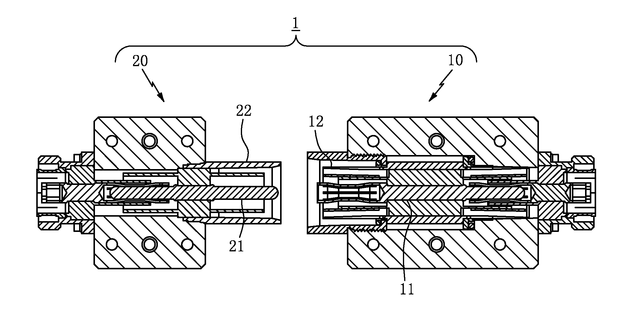
[0056]As FIG. 1 shows, a coaxial connector 1 of this embodiment includes a receptacle unit 10 equipped with a female contact portion and a plug unit 20 equipped with a male contact portion. Each contact portion includes a rod-shaped center conductor and a tubular outer conductor that surrounds the circumference of the center conductor almost entirely along the lengthwise direction of the center conductor. Each of the receptacle unit 10 and the plug unit 20 allows a coaxial cable to be connected to the base-end side thereof.

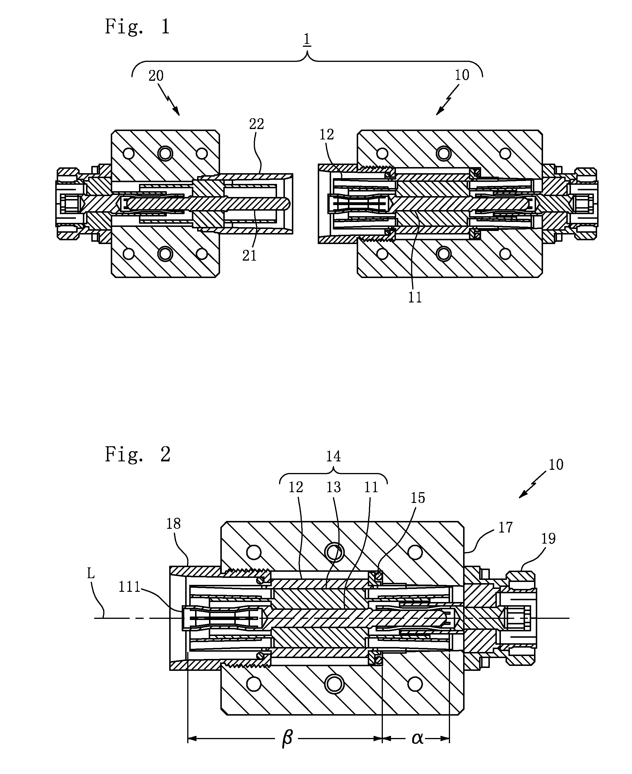
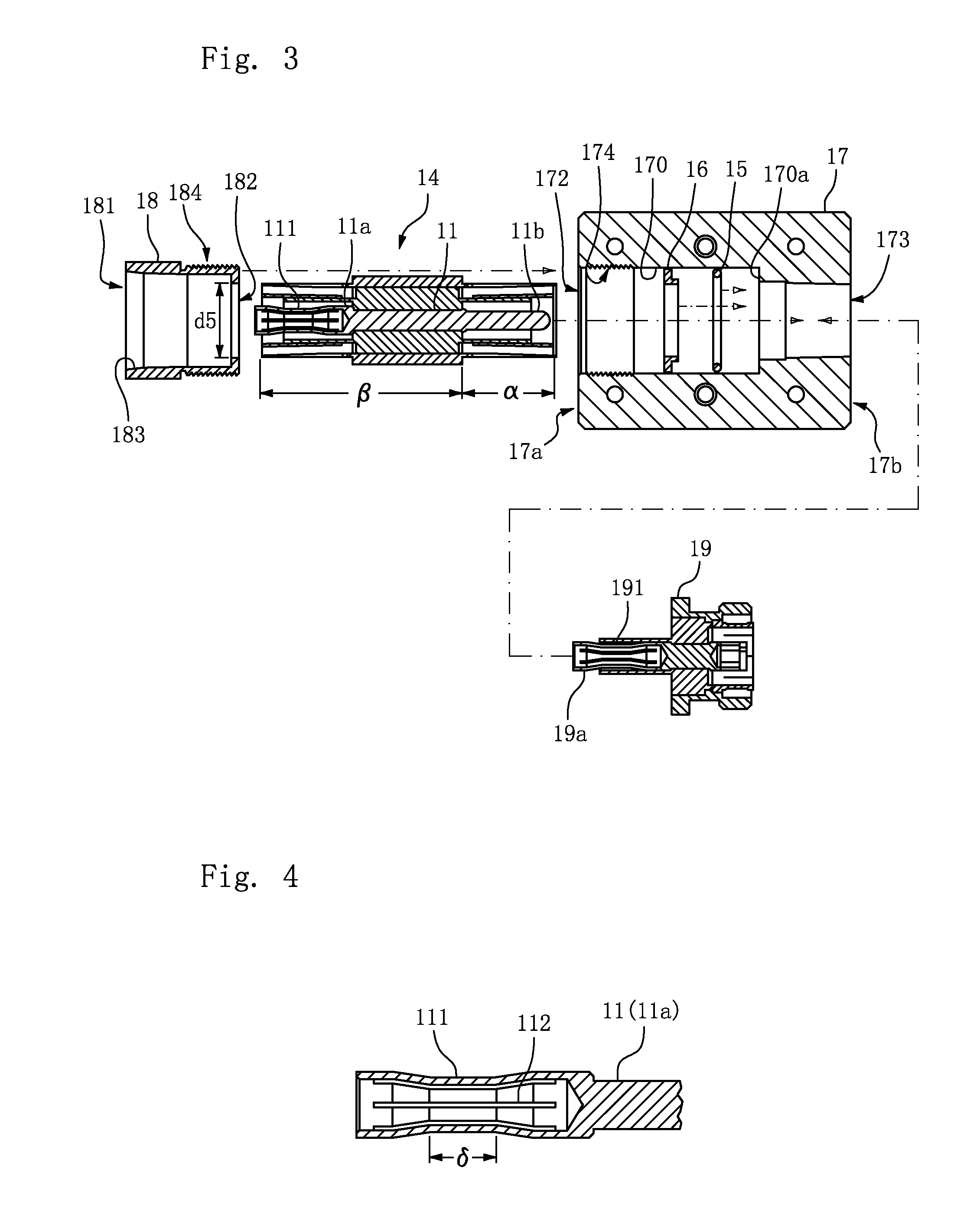
[0057]As FIGS. 2 and 3 show, the receptacle unit 10 includes a contact-section portion 14, a housing 17, a plug receptor portion 18, and a coaxial-cable fixing connector portion 19.

[0058]The contact-section portion 14 includes a center conductor 11 and an outer conductor 12 that are to be electrically connected to the plug unit 20, and an insulator 13 provided between the center conductor 11 and the outer conductor 12. The conductors 11 and 12, and the insulator 1...

embodiment 2

[0117]The invention is capable of making the contact-section portion 14 incline in a more flexible manner.

[0118]Specifically, as FIGS. 2 and 3 show, this embodiment differs from Embodiment 1 in that a spacer 15 is disposed between the large-diameter portion 121 of the outer conductor 12 in the contact-section portion 14 and a floor portion 170a of the pitted accommodating portion 170 included in the housing 17.

[0119]Note that in each of the other embodiments that follow, the description focuses on those portions that are different from the case of Embodiment 1. Thus, constituent portions similar to those in Embodiment 1 are denoted by the same reference numerals, and the description of such portions will not be given. Those portions with the same reference numerals across various embodiments are identical to each other unless noted otherwise.

[0120]The spacer 15 creates a predetermined distance (gap) between the large-diameter portion 121 of the outer conductor 12 in the contact-sect...

embodiment 3

[0127]The invention is capable of making the contact-section portion 14 incline in an even more flexible manner.

[0128]Specifically, as FIG. 15 shows, this embodiment differs from each of the above-described embodiments in that the base-end-side supporting pieces 124 of the outer conductor 12 in the contact-section portion 14 are each formed into a tapered shape with a thickness decreasing towards the base end portion 12b.

[0129]Since the base-end-side supporting pieces 124 of the outer conductor 12 in the contact-section portion 14 are each formed in a tapered shape, the base-end-side supporting pieces 124 can incline radially in a more flexible manner, and the leading-end-side un-supported region β of the outer conductor 12 in the contact-section portion 14 can incline more easily.


PUM


Abstract

Provided is a technique to connect connectors that electrically connect coaxial cables to each other, the technique capable of reducing errors in manual work and improving work efficiency by making the work easier and simpler. Plural slots 123 each extending in an axial direction are provided in a base-end-side supporting region α of an outer conductor 12 of a contact-section portion 14. Base-end-side supporting pieces 124 deformable radially are formed by the slots. The base-end-side supporting region of the contact-section portion is attached to the inside of a supporting tubular portion 171 of a housing 17, and thereby a leading-end-side un-supported region β that is not supported by the housing is allowed to incline with respect to the axial direction.

Description

BACKGROUND OF THE INVENTION[0001]1. Field of the Invention[0002]The invention relates to a cable connector to electrically connect cables to each other, and specifically to a coaxial connector with a structure capable of electrically connecting coaxial cables to each other without requiring any manual work when a connection system for transmitting radio-frequency power is built.[0003]2. Description of the Related Art[0004]In recent years, a growing number of processes of manufacturing electrical apparatuses have used radio-frequency power. In addition, there is a tendency that the frequency and magnitude of the power used for this purpose have become higher and higher. Transmission of radio-frequency power in such manufacturing processes needs transmission lines with the above-described coaxial structure to take advantage of the efficiency of the radio-frequency power transmission. Transmission lines of coaxial structure are connected to each other with special cable connectors call...

Claims


Application Information

Patent Timeline
Patent Type & Authority Patents(United States)
IPC IPC(8): H01R9/05
CPCH01R13/6315H01R24/54
Inventor IGARASHI, SATOSHIMATSUDO, TOSHIYA
Owner GV TECH
Why Eureka
Try Eureka