
Carrier frequency estimation method and apparatus in wireless communication system
a wireless communication system and carrier frequency estimation technology, applied in wireless communication, synchronisation arrangement, amplitude demodulation, etc., can solve the problems of deteriorating frequency offset estimation performance, significant bit error rate (ber), and more vulnerable ofdm system to carrier frequency offset, so as to improve the accuracy of carrier frequency offset estimation
- Summary
- Abstract
- Description
- Claims
- Application Information
AI Technical Summary
Benefits of technology
Problems solved by technology
Method used
Image

Examples
Embodiment Construction
[0032]Exemplary embodiments of the present invention are described with reference to the accompanying drawings in detail. The same reference numbers are used throughout the drawings to refer to the same or like parts. Detailed descriptions of well-known functions and structures incorporated herein may be omitted to avoid obscuring the subject matter of the present invention.
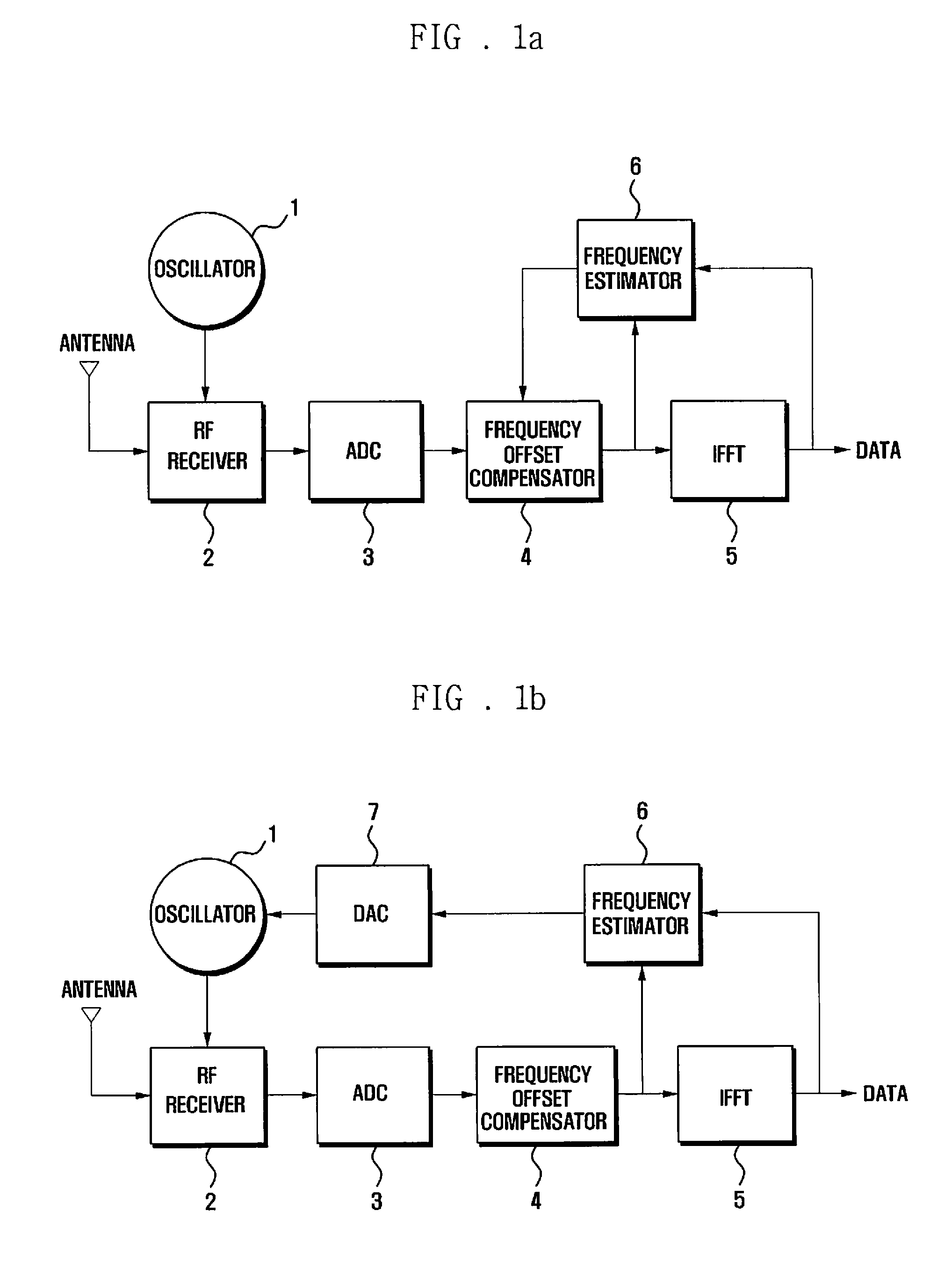
[0033]FIG. 1a is a diagram illustrating a configuration of a receiver according to an embodiment of the present invention.
[0034]As shown in FIG. 1a, the receiver includes an oscillator 1 for generating an oscillation frequency, a Radio Frequency (RF) receiver 2 for receiving an RF signal by means of an antenna in tune with the oscillation frequency, an Analog to Digital Converter (ADC) 3 for converting the received RF signal into a digital signal, a frequency offset compensator 4 for compensating the frequency offset of the digital signal, an Inverse Fast Fourier Transformer (IFFT) 5 for performing inverse Fast F...
PUM
 Abstract
Description
Claims
Application Information