Method for providing an electronic lapping guide corresponding to a near-field transducer of an energy assisted magnetic recording transducer

a technology of energy assisted magnetic recording and electronic lapping guide, which is applied in the direction of lapping machines, instruments, manufacturing tools, etc., can solve the problems of difficult fabrication of conventional transducers, difficult control using conventional manufacturing methods,

Active Publication Date: 2013-02-19
WESTERN DIGITAL TECH INC
View PDF87 Cites 170 Cited by
  • Summary
  • Abstract
  • Description
  • Claims
  • Application Information

AI Technical Summary

Problems solved by technology

Such control may be difficult to achieve using conventional manufacturing methods.
Thus, fabrication of the conventional transducer 10 may be challenging.

Method used


Image

  • Method for providing an electronic lapping guide corresponding to a near-field transducer of an energy assisted magnetic recording transducer
  • Method for providing an electronic lapping guide corresponding to a near-field transducer of an energy assisted magnetic recording transducer
  • Method for providing an electronic lapping guide corresponding to a near-field transducer of an energy assisted magnetic recording transducer

Examples


Embodiment Construction

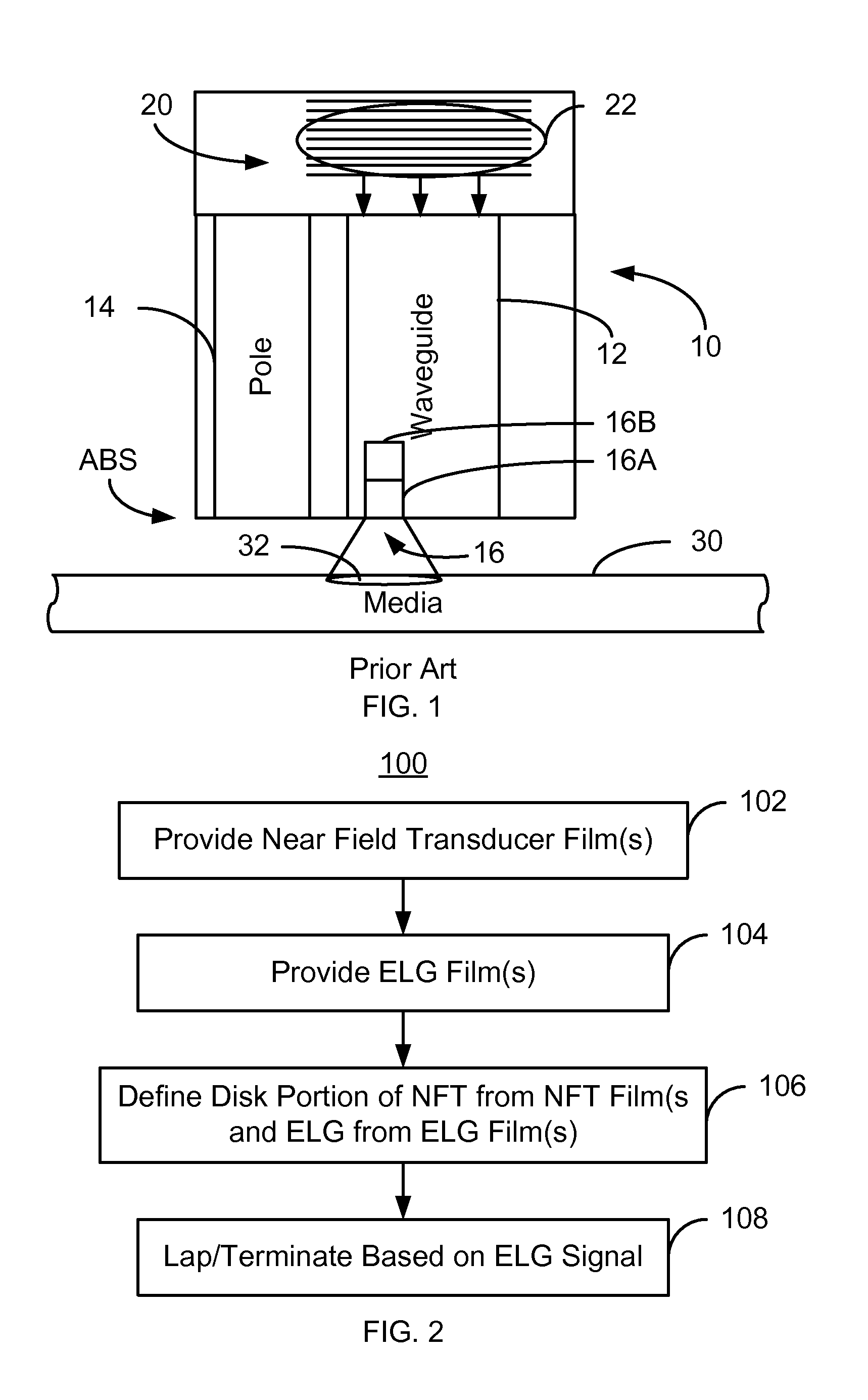
[0012]FIG. 2 is an exemplary embodiment of a method 100 for providing an EAMR transducer including a near-field transducer (NFT). For simplicity, some steps may be omitted. The method 100 is described in the context of providing a single EAMR transducer. However, the method 100 may be used to fabricate multiple transducers at substantially the same time. The method 100 is also described in the context of particular structures. A structure or layer may include multiple materials and / or multiple sub-layers and may be formed using multiple sub-steps. Further, the method is described in the context of one electronic lapping guide (ELG) corresponding to one transducer. However, in some embodiments, one ELG may correspond to multiple transducers. Alternatively, a single transducer may correspond to multiple ELGs. The method 100 also may start after formation of other portions of the EAMR transducer. For example, the method 100 may commence after formation of a read transducer and a wavegu...


PUM

PropertyMeasurementUnit
critical dimensionaaaaaaaaaa
energyaaaaaaaaaa
shapeaaaaaaaaaa

Abstract

A method fabricates a transducer having an air-bearing surface (ABS). The method includes providing at least one near-field transducer (NFT) film and providing an electronic lapping guide (ELG) film substantially coplanar with a portion of the at least one NFT film. The method also includes defining a disk portion of an NFT from the portion of the at least one NFT film and at least one ELG from the ELG film. The disk portion corresponds to a critical dimension of the NFT from an ABS location. The method also includes lapping the at least one transducer. The lapping is terminated based on a signal from the ELG.

Description

BACKGROUND[0001]FIG. 1 depicts a portion of a conventional energy assisted magnetic recording (EAMR) transducer 10. The conventional EAMR transducer 10 is used in writing to recording media 30. To do so, the conventional EAMR transducer 10 receives light, or energy, from a conventional laser (not shown in FIG. 1). The conventional EAMR transducer 10 includes a conventional waveguide 12, conventional pole 14, and a conventional near-field transducer (NFT) 16, as well as a grating 20. The conventional NFT 16 includes a disk portion 16B and a pin portion 16A. The disk portion 16B is wider in the direction perpendicular to the plane of the page than the pin portion 16A. Although termed a “disk portion”, the portion 16B may have a shape other than a circle. Also shown is a laser spot 22 on the grating 20. Other components that may be part of the conventional EAMR transducer 10 are not shown.[0002]In operation, the light from the spot 22 on the grating 20 is coupled to the conventional wa...

Claims


Application Information

Patent Timeline
Patent Type & Authority Patents(United States)
IPC IPC(8): G11B5/127H04R31/00
CPCB24B37/013G11B5/314G11B5/3169G11B13/04G11B2005/001G11B2005/0021Y10T29/49043Y10T29/49048Y10T29/49046Y10T29/49044Y10T29/49041Y10T29/49052
Inventor HU, YUFENGWANG, ZHONGYANLI, JINSHAN
Owner WESTERN DIGITAL TECH INC
Why Eureka
Try Eureka