Apparatus and method for compensating images for differences in aspect

a technology of image and aspect, applied in the field of radioactive imaging, can solve the problem that the echoes returned from the same object will vary depending on the object, and achieve the effect of reducing or eliminating the aspect dependence of radar/sonar echoes

Active Publication Date: 2013-02-19
USA AS REPRESENTED BY THE SEC OF THE NAVY THE
View PDF2 Cites 6 Cited by
  • Summary
  • Abstract
  • Description
  • Claims
  • Application Information

AI Technical Summary

Benefits of technology

[0005]Accordingly, an object of the invention is to reduce or eliminate aspect dependence of radar / sonar echoes returned from the same object, or from highly similar objects.
[0006]Another object is to reduce or eliminate aspect dependence in feature based navigation.

Problems solved by technology

A fundamental problem in sonar or radar imaging is that the echoes returned from the same object will differ depending on the aspect at which the sonar or radar radiatively scans the object.

Method used


Image

  • Apparatus and method for compensating images for differences in aspect
  • Apparatus and method for compensating images for differences in aspect
  • Apparatus and method for compensating images for differences in aspect

Examples


Embodiment Construction

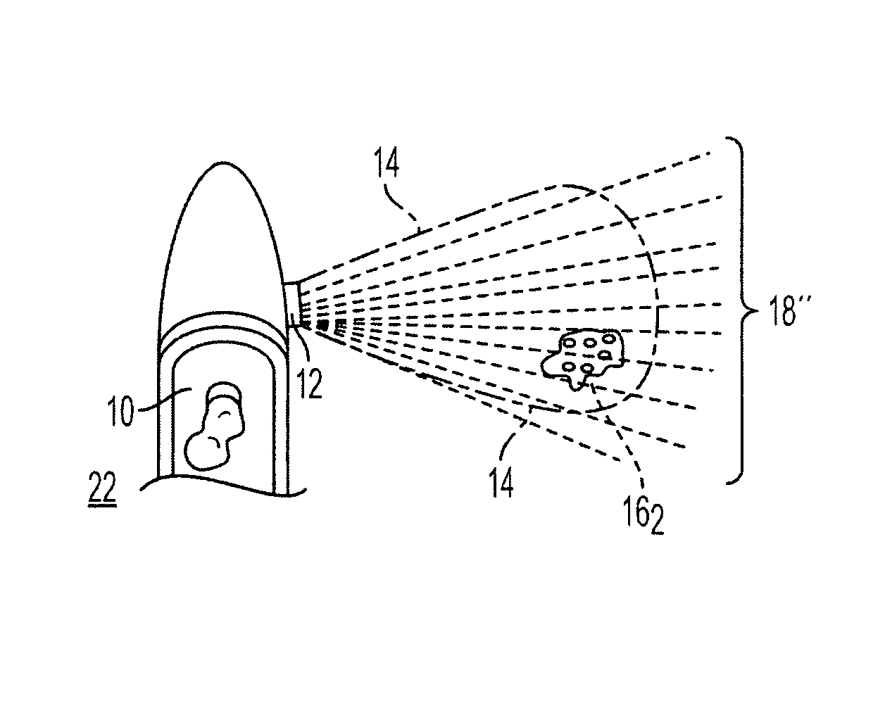
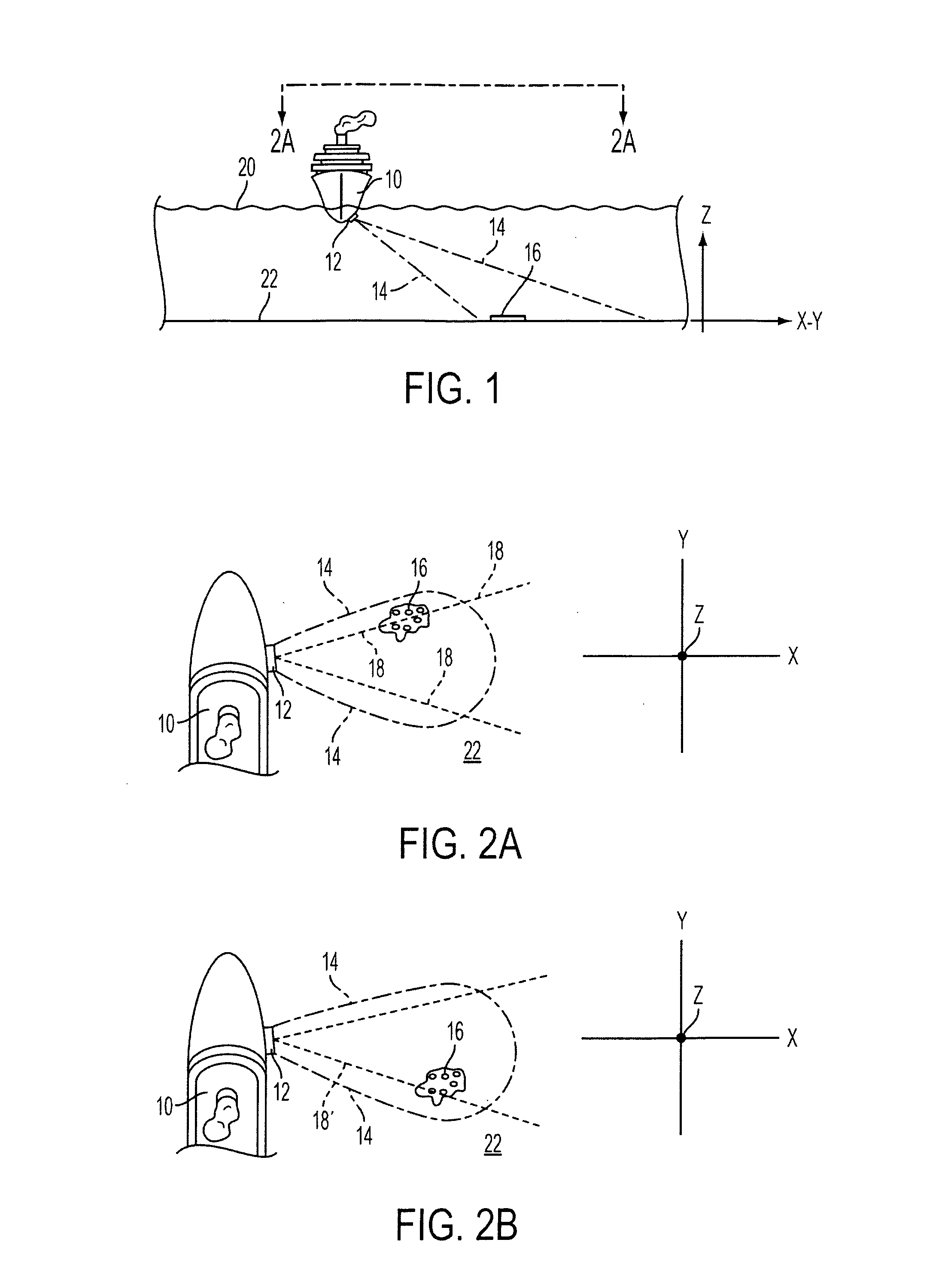
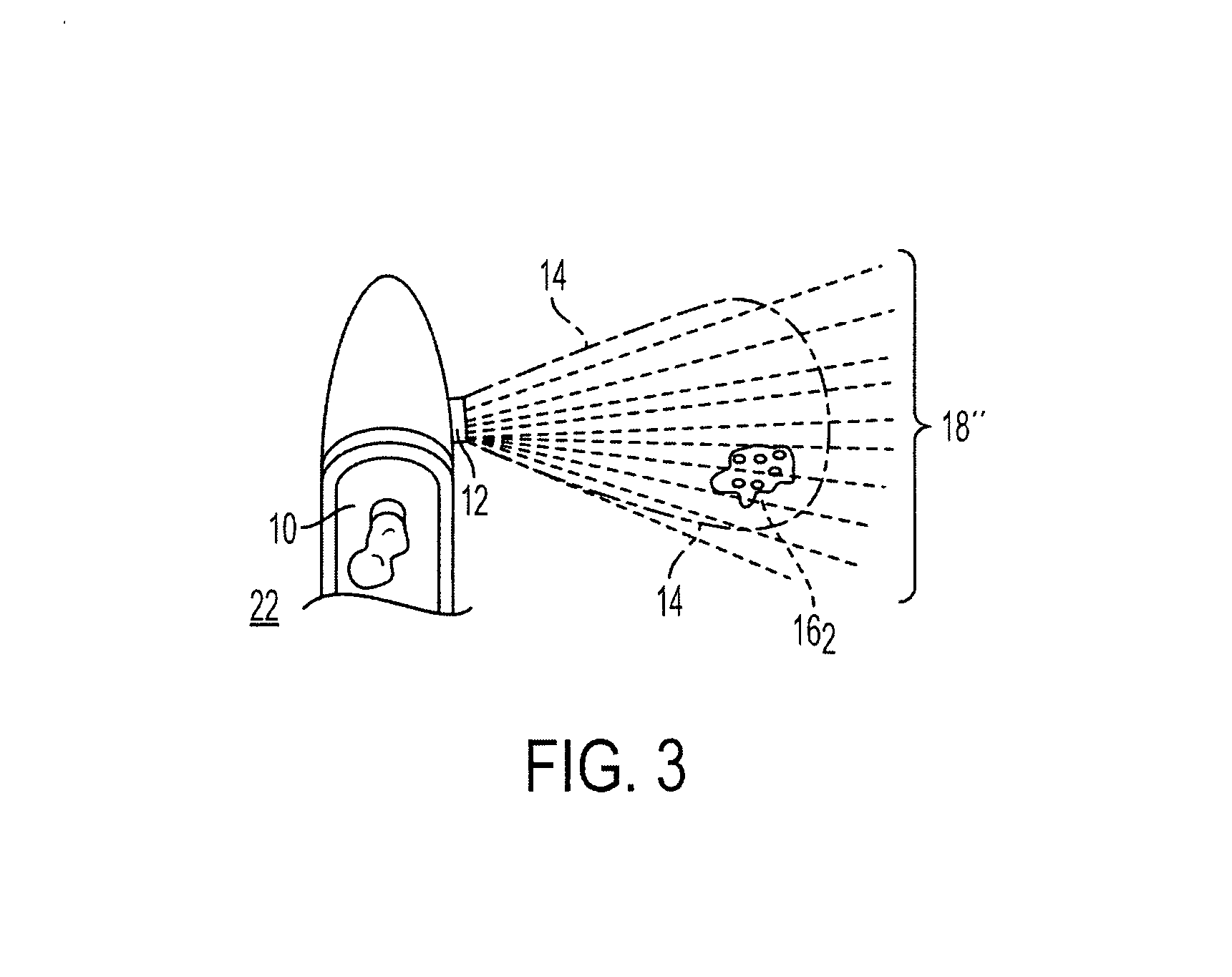
[0013]With reference to the drawing figures, wherein like numbers indicate like parts throughout the several views, FIG. 1 shows a ship 10 on surface 20 with a side scanning sonar 12. FIG. 1 also shows a set of reference axes marked z, indicating altitude above marine bottom 22, and x-y, indicating the plane in which marine bottom 22 lies. Sonar 12 acoustically scans marine bottom 22 with a beamwidth illustrated in FIG. 1 as having azimuthal (z axis) boundary 14. Within beamwidth 14 on marine bottom 22 is bottom patch 16 which is distinct from the surrounding portion of bottom 22. Patch16 could be, for example, areas of sea shells or pebbles, surrounded by an otherwise sandy bottom 22.

[0014]FIGS. 2a and 2b show the same scene as FIG. 1, but looking down in the direction of marine bottom 22, and with the difference between 2a and 2b being that ship 10 is at a different position with respect to bottom patch 16. In each of these drawing figures, patch 16 is located within beamwidth 14,...


PUM


Abstract

A method and apparatus for eliminating aspect dependence of images generated by a radiative scanner such as a radar, sonar, or the like. Echoes from the scanner are received back and detected at a known and preselected number of aspects. The echo received at each aspect is multiplied by the transform of the point spread function of each of the other preselected aspects. In this manner, the frequency domain version of each echo is multiplied by the frequency domain point spread function of all of the preselected aspects, and the ultimate processed echo will be aspect independent.

Description

CLAIM OF PRIORITY[0001]This application has the priority of U.S. Provisional Patent Application Ser. No. 61 / 216,566, filed May 18, 2009, which is currently pending.STATEMENT OF GOVERNMENT INTEREST[0002]The invention described herein may be manufactured and used by or for the Government of the United States of America for governmental purposes without the payment of any royalties thereon or therefor.FIELD OF THE INVENTION[0003]The Invention pertains to radiative imaging, such as by radar or sonar, and feature based navigation.BACKGROUND OF THE INVENTION[0004]A fundamental problem in sonar or radar imaging is that the echoes returned from the same object will differ depending on the aspect at which the sonar or radar radiatively scans the object. This is of special concern to a class of problems collectively named feature based navigation, in which a vessel, such as an ocean going ship, submersible platform, helicopter or airplane, or the like, compares echoes it receives to a pre-exi...

Claims


Application Information

Patent Timeline
Patent Type & Authority Patents(United States)
IPC IPC(8): G01S15/00
CPCG01S7/292G01S7/5273G01S13/89G01S15/8902G01S15/89G01S7/41G01S7/539
Inventor RIKOSKI, RICHARD J.
Owner USA AS REPRESENTED BY THE SEC OF THE NAVY THE
Why Eureka
Try Eureka