Waveguide structures and methods

a waveguide and structure technology, applied in the field of waveguides, can solve the problems of increasing the crosstalk between adjacent communication channels, adverse effects, and rate errors

Inactive Publication Date: 2005-12-29
XEROX CORP
View PDF2 Cites 7 Cited by
  • Summary
  • Abstract
  • Description
  • Claims
  • Application Information

AI Technical Summary

Benefits of technology

[0001] Embodiments herein generally relate to waveguides that are used to direct and control light. Light has two polarizations, and can propagate in a media (such as a silicon waveguide) at two different speeds for the two polarizations. For a rib/ridge waveguide, the two polarized modes are generally referred to as the transverse electric (TE) and transverse magnetic (TM) modes. The two modes may see the same media differently, as the effective refractive index for the two polarizations may di

Problems solved by technology

The difference in the refractive index of the two polarizations can cause various adverse effects for an optical communication system and if this difference is not properly compensated for, it will cause adverse effects such as polarization mode dispersion that causes bit rate errors.
Such a shift will increase the crosstalk between adjacent communication channels and limit bandwidth.
For λ0=1550 nm, and, nte≈3.42, as typically used, a small difference in nte and ntm could result in significant performance

Method used


Image

  • Waveguide structures and methods
  • Waveguide structures and methods
  • Waveguide structures and methods

Examples


Embodiment Construction

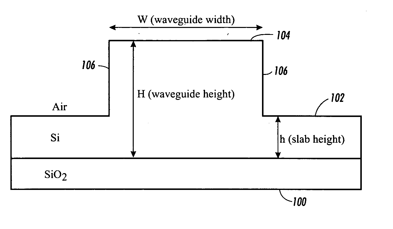
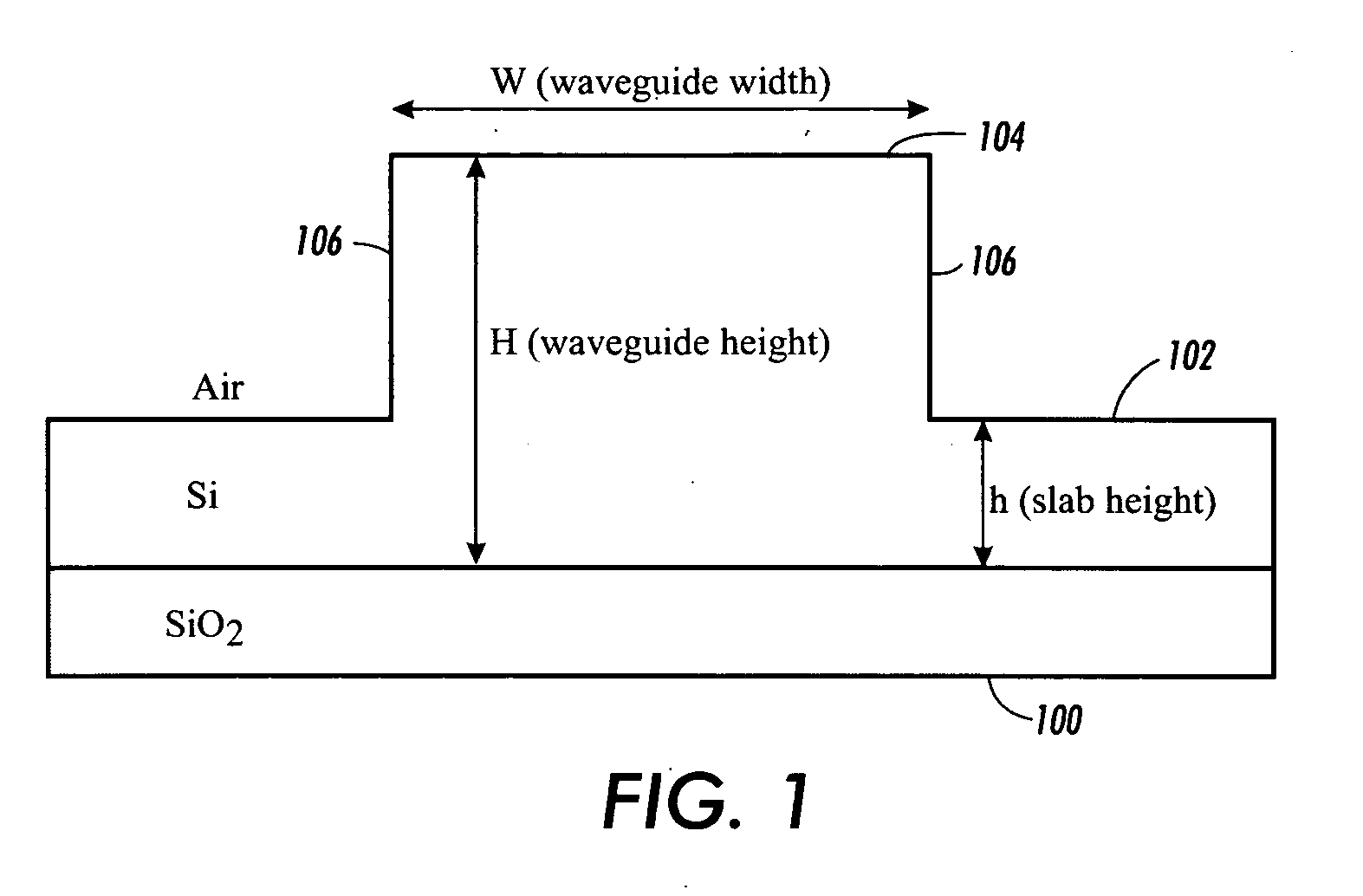
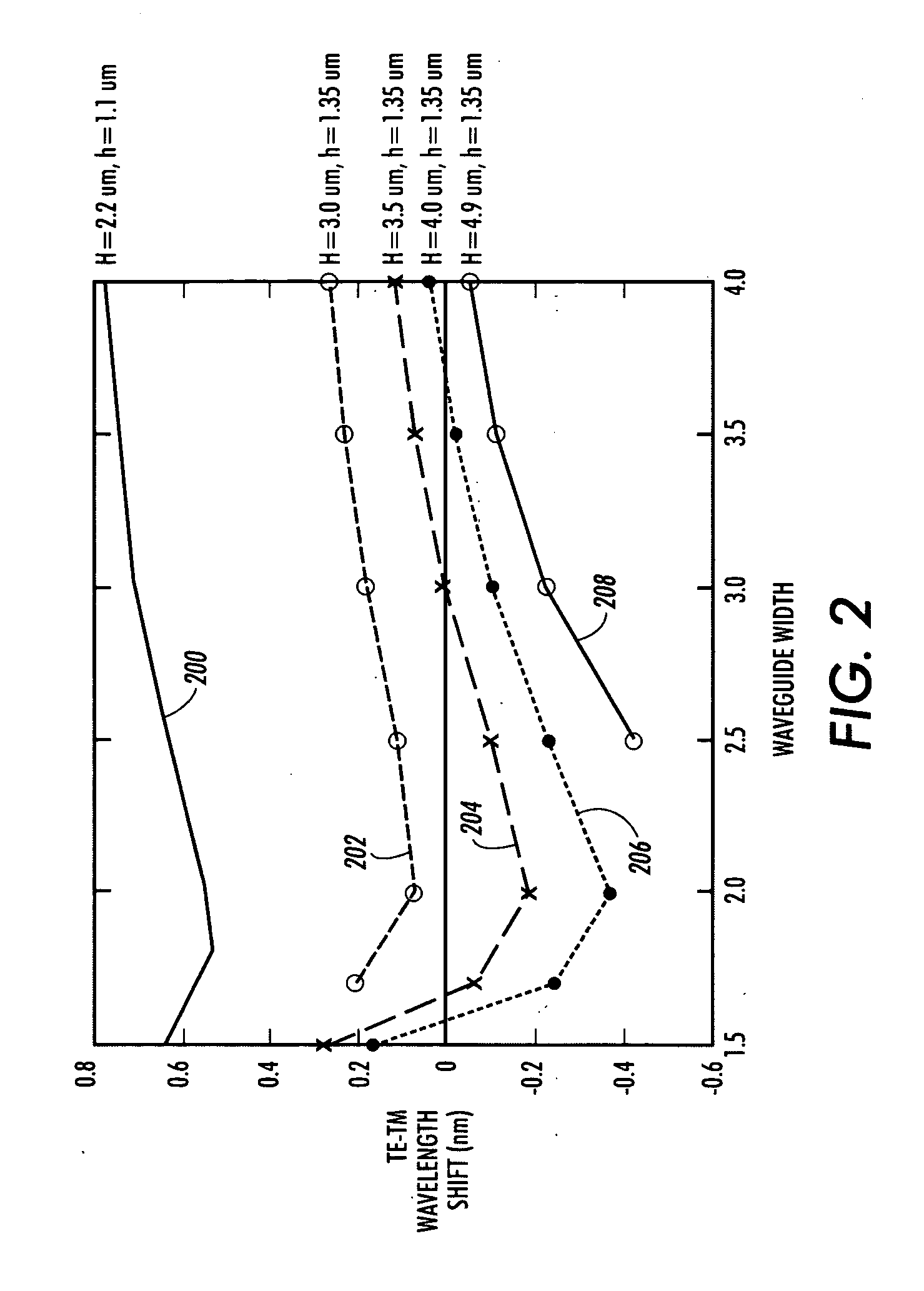
[0016] According to various exemplary embodiments of systems and methods illustrated herein, a polarization insensitive design space for waveguides and arrayed waveguide grating systems and can be used in, for example, silicon-on-insulator (SOI) micro electromechanical system (MEMS) technology to compensate and to minimize bit rate errors and crosstalk. This polarization insensitive waveguide structure is the basic building block of many components such as an AWG and a switch. These components are the building blocks of many optical network components such as routers and optical add / drop multiplexers that are used by many wavelength division multiplexing (WDM) and dense wavelength division multiplexing (DWDM) technologies. The base geometry can be T-shaped in cross-section, as shown in FIG. 1, and has optimum width and height parameter ranges. By optimizing the ratio between the width and height of the waveguide and the height of base, the TE-TM wavelength shift is minimized to with...


PUM


Abstract

A waveguide structure has a base having a base height (h) above a substrate and a rectangular waveguide having a waveguide height (H) above the substrate and a waveguide width (W) between opposing sides of the waveguide.

Description

BACKGROUND AND SUMMARY [0001] Embodiments herein generally relate to waveguides that are used to direct and control light. Light has two polarizations, and can propagate in a media (such as a silicon waveguide) at two different speeds for the two polarizations. For a rib / ridge waveguide, the two polarized modes are generally referred to as the transverse electric (TE) and transverse magnetic (TM) modes. The two modes may see the same media differently, as the effective refractive index for the two polarizations may differ. The difference in the effective refractive index could be the result of the symmetry of the media, or, in the case of silicon waveguides, the result of different boundary conditions for the two polarizations. The difference in the refractive index of the two polarizations can cause various adverse effects for an optical communication system and if this difference is not properly compensated for, it will cause adverse effects such as polarization mode dispersion th...

Claims


Application Information

Patent Timeline
IPC IPC(8): G02B6/10G02B6/122
CPCG02B6/122G02B6/105
Inventor GERMAN, KRISTINE A.GULVIN, PETER M.KUBBY, JOEL A.LIN, PINYENLIU, XUEYUANWANG, YAO RONG
Owner XEROX CORP
Why Eureka
Try Eureka