Wavelength-dispersive X-ray spectrometer

a spectrometer and wavelength-dispersive technology, applied in the direction of material analysis using wave/particle radiation, instruments, nuclear engineering, etc., can solve the problems of inability to easily put into practical use, inability to achieve easy application, and inability to meet the requirements of the application of the material, so as to improve the ratio of the intensity of characteristic x-rays to the background intensity, the effect of deteriorating the spectrally selective performan

Inactive Publication Date: 2010-11-11
JEOL LTD
View PDF1 Cites 33 Cited by
  • Summary
  • Abstract
  • Description
  • Claims
  • Application Information

AI Technical Summary

Benefits of technology

[0023]According to the present invention, when an analysis is made using a curved analyzing crystal which is mounted in a wavelength-dispersive X-ray spectrometer designed to collect X-rays diffracted by the curved analyzing crystal while moving the crystal straight, a limitation device is mounted integrally with the curved analyzing crystal. The direction of angular dispersion of the crystalline lattice plane of the analyzing crystal has a curvature equal to the diameter of the Rowland circle. The surface of the curved analyzing crystal has an effective diffractive region contributing to actual diffraction. As the spectral position of the X-ray spectrometer varies, the effective diffractive region varies. Correspondingly, the limitation device limits at least one of the incident regions of the surface of the curved analyzing crystal from which incident X-rays enter and the exit region of the surface of the analyzing crystal from which X-rays are diffracted toward the X-ray detector such that only X-rays diffracted by the effective diffractive region of the surface of the analyzing crystal are detected by the X-ray detector. Consequently, only the X-rays diffracted by the effective diffractive region of the surface of the curved analyzing crystal can be guided to the X-ray detector at all times for every wavelength of X-rays within the spectral range without the need for the operator to make any decision or perform any manipulation. As a result, X-rays on portions not contributing to diffraction can be prevented; otherwise, abnormal waveforms would be produced and the spectrally selective performance would be deteriorated. Hence, the wavelength resolution of characteristic X-rays used for analysis and the ratio of the intensity of the characteristic X-rays to the background intensity can be improved.

Problems solved by technology

Therefore, some analyzing crystals for relatively long wavelengths have deteriorated performance and thus cannot be easily put into practical use.
However, there is the problem that spatial restrictions are inevitably imposed when a wide slit is placed.
Therefore, a spherically-curved, Johann-type analyzing crystal fabricated to match the length suitable for one wavelength of characteristic X-rays of interest within the analyzed range cannot be suitably used for spectral analysis of other characteristic X-rays which are widely different in wavelength from the X-ray to be selected.
In very bad cases, lumpy hills appear on the waveform.
This may impair the reliability of the waveform itself.
Furthermore, there is the problem that the total area of the analyzing crystal is narrower than the effective diffraction area for characteristic X-rays longer than the X-rays to be spectrally selected, giving rise to a loss of the detectable X-ray intensity.
In an ordinary curved crystal, there is the problem that X-rays enter even those portions which do not contribute to diffraction, deteriorating the wavelength resolution of the detected X-rays and the ratio of the intensity of the characteristic X-rays to the background intensity.
However, it is not easy for the operator to select an X-ray takeoff window of appropriate size.
Consequently, there is the problem that it is laborious to switch the X-ray takeoff window by manual manipulations.
Furthermore, it is impossible to cope with continuous variation of X-ray wavelength.

Method used


Image

  • Wavelength-dispersive X-ray spectrometer
  • Wavelength-dispersive X-ray spectrometer
  • Wavelength-dispersive X-ray spectrometer

Examples


specific embodiment

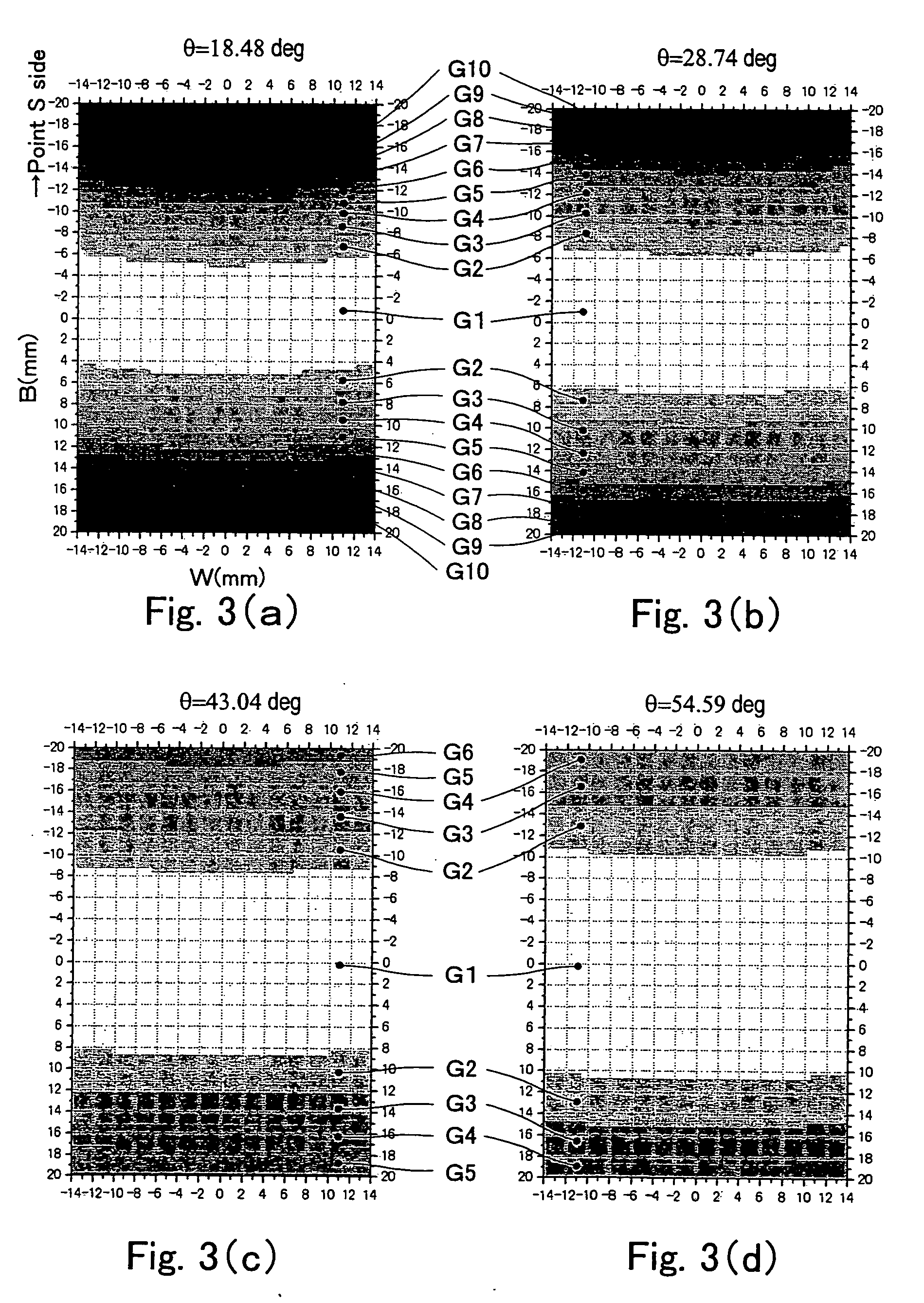
[0049]An example in which the height of the X-ray blocking plate was found under the conditions where R=140 mm and a=20 mm by the aforementioned method is described below. b is the distance on the side of the X-ray generation point S in the direction of angular dispersion under the actual conditions where the incident angle error a enables regions G1-G3 and where region G4 and the following regions are shielded by the X-ray blocking plate. The results of calculation are shown in Table 2.

TABLE 2incident angle θ (in degrees)18.4828.7443.0454.59averageb (mm)8.310.814.317.9—h (mm)4.45.76.34.05.1h1 (mm)3.75.05.63.34.4

[0050]As shown in Table 2, the required height of the X-ray blocking plate can be determined from data obtained by calculating the incident angle error Δθ. Meanwhile, the results shown in Table 2 indicate that if the height h of the X-ray blocking plate or h1 is determined such that effective diffractive regions having similar levels of incident angle error Δθ are set, the v...


PUM


Abstract

An X-ray spectrometer which uses at least one curved analyzing crystal and which provides improved wavelength resolution of characteristic X-rays used for analysis and improved ratio of characteristic X-rays to background intensity by using only effective diffractive regions of the analyzing crystal. X-ray blocking plates upstand from an end of a crystal support member supporting the analyzing crystal in the direction of angular dispersion of the crystal toward the inside of a Rowland circle. Incident X-rays going from the point X-ray source toward the crystal and X-rays diffracted by the crystal toward an X-ray detector are partially blocked by the X-ray blocking plates. The shielded regions vary according to the incident angle θ of the incident X-rays. Optimum or nearly optimum effective regions of the surface of the crystal can be used at all times.

Description

BACKGROUND OF THE INVENTION[0001]1. Field of the Invention[0002]The present invention relates to a wavelength-dispersive X-ray spectrometer used in an electron probe microanalyzer (EPMA) or other similar instrument and, more particularly, to a technique for improving the performance of an X-ray spectrometer equipped with analyzing crystals curved in the direction of angular dispersion.[0003]2. Description of Related Art[0004]EPMAs are widely used as instruments for qualitatively and quantitatively analyzing a sample by sharply focusing an accelerated electron beam, directing the beam toward a surface of the sample, dispersing the generated characteristic X-rays, and analyzing the sample from the wavelengths and intensities of the dispersed X-rays. Generally, an EPMA is equipped with a wavelength-dispersive (WD) spectrometer designed to collect X-rays while moving the crystal along a straight path. This X-ray spectrometer may be hereinafter referred to as the WD spectrometer of the s...

Claims


Application Information

Patent Timeline
Patent Type & Authority Applications(United States)
IPC IPC(8): G01T1/36
CPCG01N23/2252G21K1/06G21K2201/062H01J2237/24425G21K2201/067H01J37/244H01J37/252G21K2201/064
Inventor KAWABE, KAZUYASU
Owner JEOL LTD
Why Eureka
Try Eureka