
Wavelength-dispersive X-ray spectrometer
a spectrometer and wavelength-dispersive technology, applied in the direction of material analysis using wave/particle radiation, instruments, nuclear engineering, etc., can solve the problems of inability to easily put into practical use, inability to achieve easy application, and inability to meet the requirements of the application of the material, so as to improve the ratio of the intensity of characteristic x-rays to the background intensity, the effect of deteriorating the spectrally selective performan
- Summary
- Abstract
- Description
- Claims
- Application Information
AI Technical Summary
Benefits of technology
Problems solved by technology
Method used
Image

Examples
specific embodiment
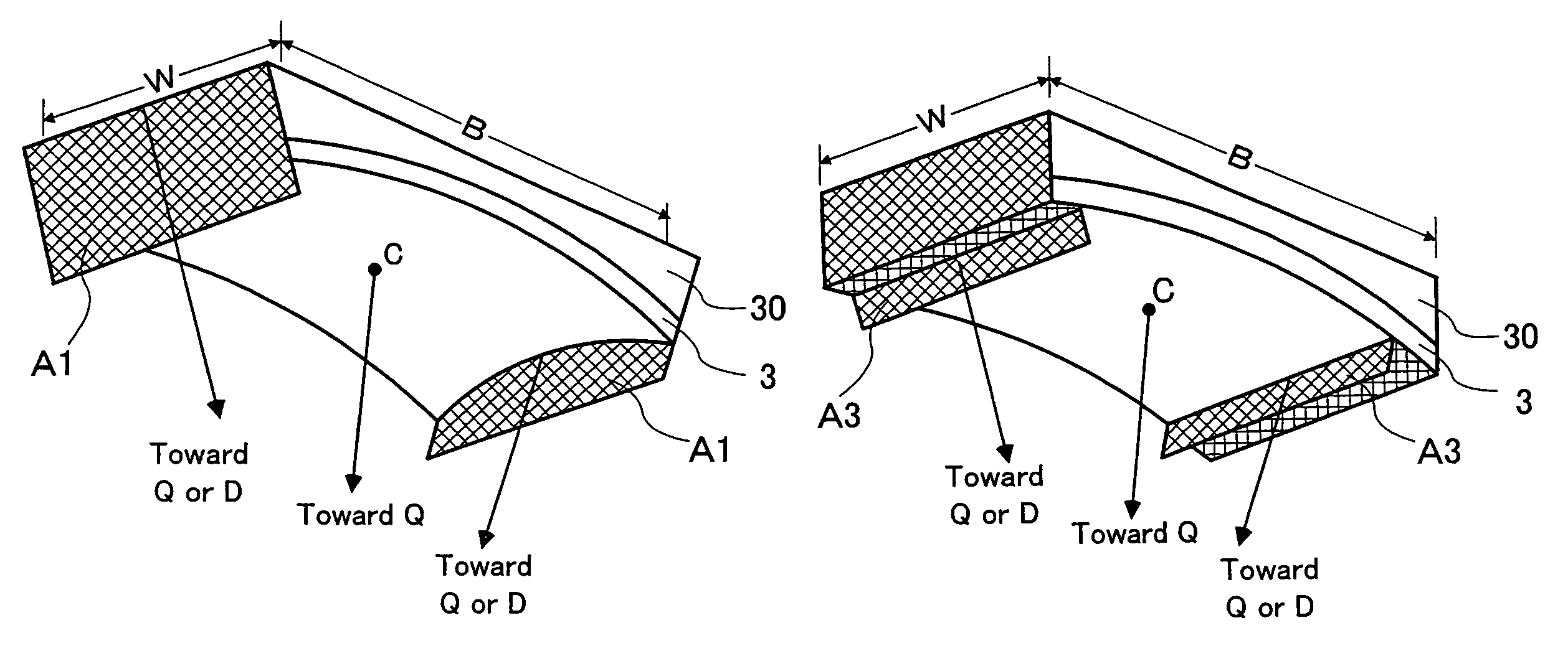
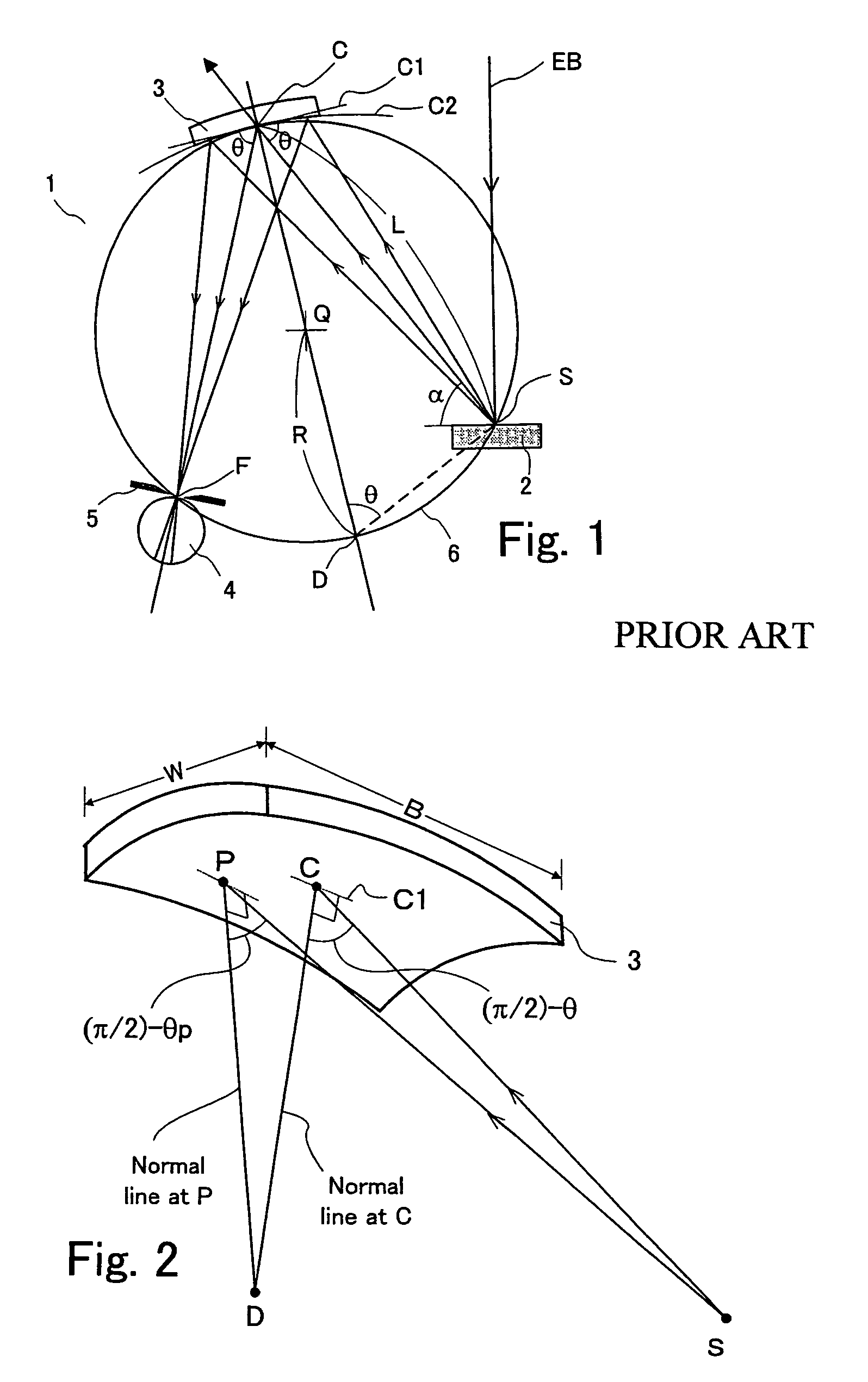
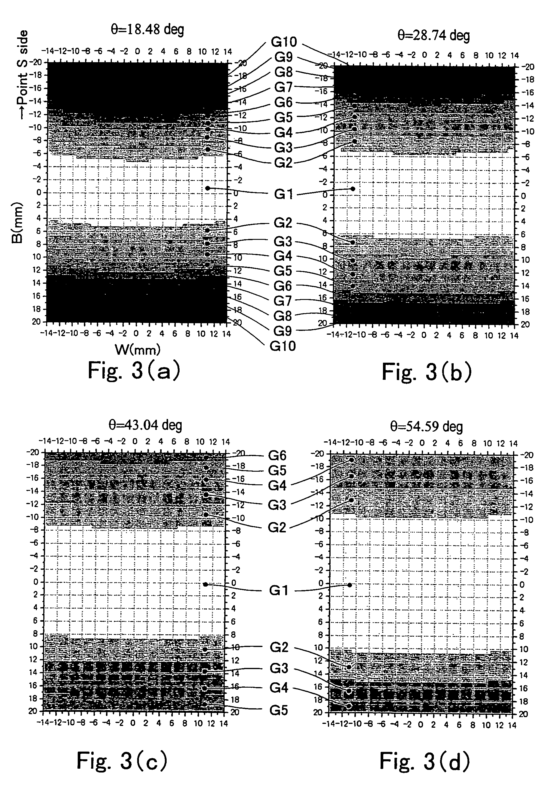
[0055]An example in which the height of the X-ray blocking plate was found under the conditions where R=140 mm and α=20 mm by the aforementioned method is described below. b is the distance on the side of the X-ray generation point S in the direction of angular dispersion under the actual conditions where the incident angle error Δθenables regions G1-G3 and where region G4 and the following regions are shielded by the X-ray blocking plate. The results of calculation are shown in Table 2.
[0056]
TABLE 2incident angle θ (in degrees)18.4828.7443.0454.59averageb (mm)8.310.814.317.9—h (mm)4.45.76.34.05.1h1 (mm)3.75.05.63.34.4
[0057]As shown in Table 2, the required height of the X-ray blocking plate can be determined from data obtained by calculating the incident angle error Δθ. Meanwhile, the results shown in Table 2 indicate that if the height h of the X-ray blocking plate or h1 is determined such that effective diffractive regions having similar levels of incident angle error Δθ are set,...
PUM
 Abstract
Description
Claims
Application Information